CCTV Cabling and Installation Guide, Your DVR / NVR system menus are controlled using a USB wired mouse. If you plug in a USB mouse and it is not responding, it may be related to a malfunction in the mouse itself or a need to reconnect your mouse with your system. LIMITATION Wireless mice are not supported. Wireless mice require special drivers or software to be installed in order to function. Current DVR / NVR systems do not support the required drivers and software.
Accessories: Multiple power adapters
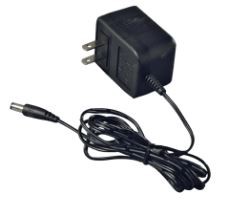
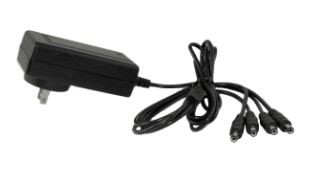
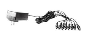
When unpacking your DVR / NVR for the first time, multiple power adapters are included. Power adapters will vary depending on the system purchased.
Adapters for the DVR / NVR:
Adapters for the cameras:
For more information on power requirements for your product, refer to your product specifications sheet. Click here for downloads and documentation for your product.
Accessories: Wired mouse not working
Your DVR / NVR system menus are controlled using a USB wired mouse. If you plug in a USB mouse and it is not responding, it may be related to a malfunction in the mouse itself or a need to reconnect your mouse with your system.
LIMITATION: Wireless mice are not supported. Wireless mice require special drivers or software to be installed in order to function. Current DVR / NVR systems do not support the required drivers and software.
To troubleshoot your mouse not responding:
Accessories: Wireless mouse not working
Wireless mice are currently not supported by DVR / NVR systems. Wireless mice require drivers and software to be installed to function. Current DVR / NVR models do not support the required drivers and software.
Wired USB mice are compatible with most DVR / NVR systems. Click here if you are having issues with a wired USB mouse not functioning.
ACR-U11W-E – 1,000 ft Cat6 CMR/FT4 UTP Communication Cable: Frequently Asked Questions
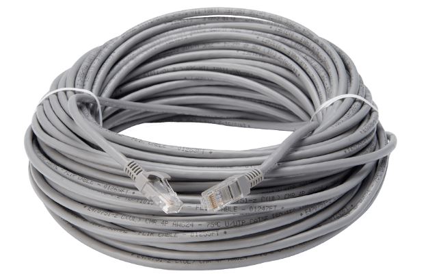
The following FAQ article answers common questions about the ACR-U11W-E 1,000 ft Cat6 CMR/FT4 UTP Communication Cable.
CCTV Cabling and Installation Guide
Also Read : Senstar License Plate Recognition Guide
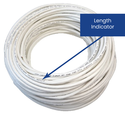
How do I know how much cable is left in the box after use?
Every 2 ft there is a marking which indicates the remaining cable length in the box. Once part of the cable has been cut, the next marking will indicate the amount of remaining cable.
Where can this cable be installed?
This cable is designed for indoor installation only and should not be used outdoors or buried underground.
Is the cable ready for use out of the package?
The cable is not ready for immediate use upon opening. It requires cutting to size and crimping with RJ45 connectors before it can be connected to an external device. Please note that RJ45 connectors are not included in the package and must be purchased separately.
What are the temperatures that the cable will work at?
-40 °F to 167 °F / -40 °C to 75 °C
What are the temperatures in which the cable can be installed?
-4 °F to 122 °F / -20 °C to 50 °C
What are the electrical characteristics of this cable?
What are the dimensions of the package?
The package dimensions are (Width × Depth × Height) 15.75 × 15.75 × 8.66” / 400 × 400 × 220 mm.
What is the weight of the package?
The weight of the package is 30.86 lb / 14 kg.
What is the cable made of?
The cable is made up of various components that consist of the following materials: the center conductor is made of solid bare copper, the insulation is made of HDPE, the rip-cord is made of nylon, the seperator is made of PE, and the outer jacket is made of CMR/FT4 ETL PVC.
Cables: BNC cable length
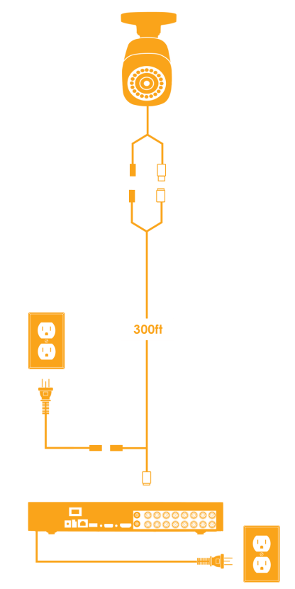
BNC cables are used for connections from the camera to a DVR. BNC cables can be run up to 300ft (91m). We recommend using one solid line from the camera to the DVR to maximize signal strength.
Cables: Digital IP vs Analog MPX extension cable setup
Lorex offers two different types of wired HD security camera systems – Digital IP and Analog MPX. Each type of system uses different technologies to provide high-definition video. The type and length of extension cables you can use depend on the type of system you have.
Digital IP NVR Systems
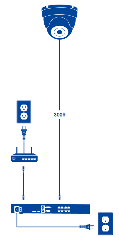
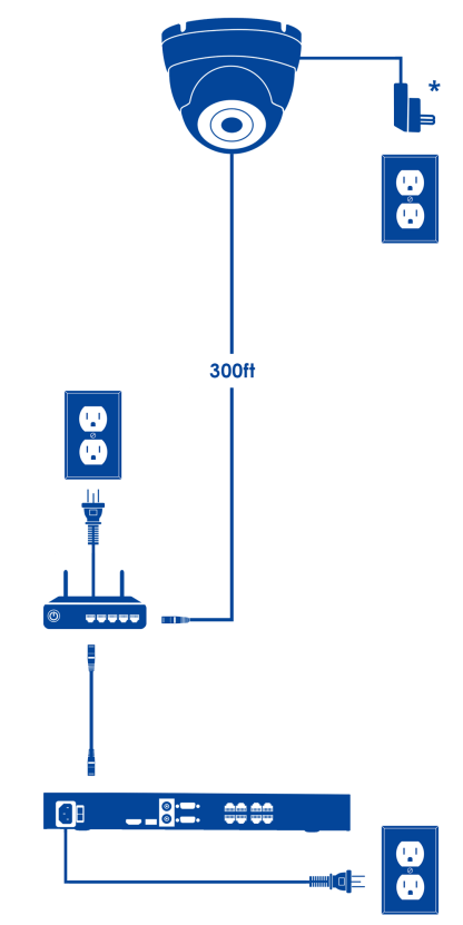
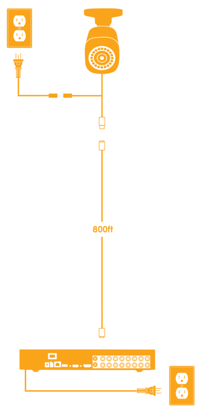
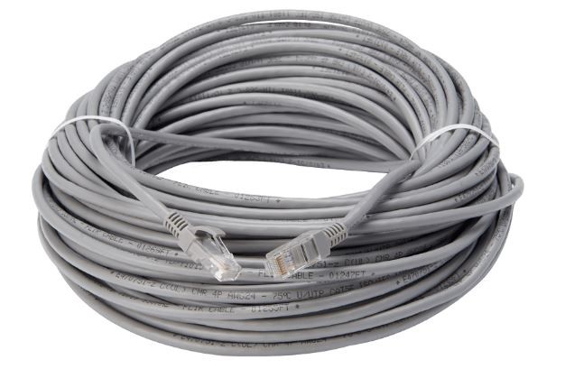
Digital IP systems use CAT5 or CAT5e (or higher) Ethernet cabling to connect IP Cameras to the network or a Network Video Recorder (NVR). This cable simultaneously transmits video and audio (if applicable) to the NVR and provides power to the camera. Click here for more information on Ethernet cable types.
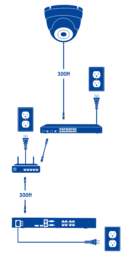
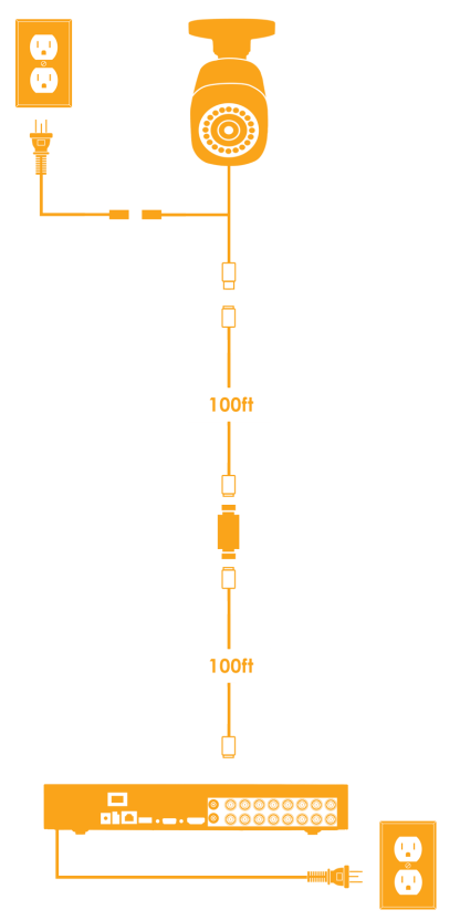
There are three different configurations of cabling that you can use with a Digital IP NVR system:
Analog MPX DVR Systems
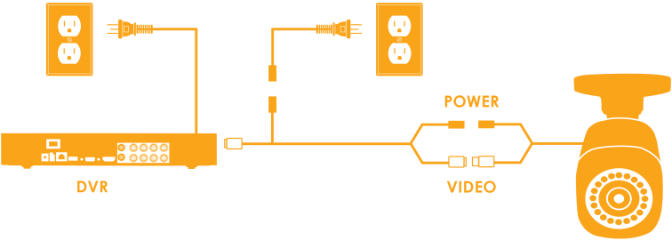
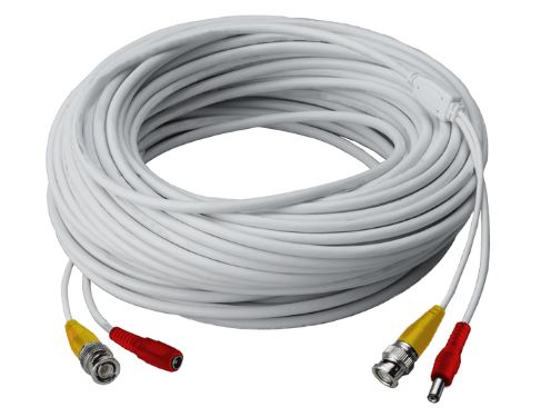
MPX security cameras transmit high-definition analog video over shielded or RG59 (or higher) BNC cables to a Digital Video Recorder (DVR). Lorex by FLIR offers siamese BNC cables, which split into two ends, one for video and one for power.
There are three different configurations of cabling that you can use with an Analog MPX DVR System:
Cables: Ethernet cable length
Ethernet cables are used to simultaneously transmit network information, video, and power from the camera to an NVR.
The maximum Ethernet cable length that can be used between an NVR and a camera is 328ft (100m). If a longer Ethernet cable is required, a Power over Ethernet (PoE) switch can be added between Ethernet cables to extend length. We recommend that only single connections be used. Multiple connections may result in signal depletion. The camera will require a power source within the first 300ft (100m) if using switches to extend Ethernet cable length. Click here for more information about different types and uses of Ethernet cables.
Cables: Ethernet cable types
Updated: Ethernet cables are widely used for wired networks, or to carry telephone and video signals. Ethernet cables extend limited distances due to their electrical transmission characteristics.
Types of Ethernet Cables
Ethernet cables vary in durability, flexibility, signal capabilities, and manufacturing costs.
Solid UTP Category Ethernet Cables
Standard UTP Category Ethernet Cables
Ethernet Cable Categories
In addition to Ethernet cable types, Ethernet cables can be categorized based on how old they are, what speeds they support, and how they mitigate signal interference.
Category 5 (Cat5)
Category 5 enhanced (Cat5e)
Category 6 (Cat6)
Cables: Preventing connector corrosion
When cables and cameras are exposed to moist and marine environments, corrosion can occur. Corrosion causes refined metals to convert a more stabilized form such as an oxide or sulfide. Cable corrosion can cause poor connection, leading to camera image issues and loss of video feed.
To prevent cable and connector corrosion:
Cables: Understanding Cable Ratings
Your DVR / NVR system will normally include 60ft or 100ft of Ethernet cables for easy set up of Lorex cameras. Before installing Ethernet cables, it is important to understand how they are rated and certified.
Ethernet Cable Ratings
The outer part of the cable, which protects the interior wires, is called a jacket. Cable ratings apply to the cable jacket and their fire-resistance ability.
To find the cable rating, check the product’s packaging or visit the product page.
CM or CMG Rating
CMR Rating
CMP Rating
Note:
Direct Burial Cables
![]() IMPORTANT: Before digging or installing these cables, be sure to contact your local building authority for local building codes and standards.
IMPORTANT: Before digging or installing these cables, be sure to contact your local building authority for local building codes and standards.
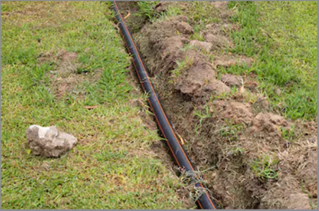
Direct burial cables are designed to be buried underground and can withstand outdoor environments. They can be used with a conduit for extra protection.
Certification
Underwriter Laboratories (UL) Cables
National Electric Code (NEC) and Canadian Electrical Code (CEC) Cables
For more information, visit the following articles:
Cables: Understanding Power over Ethernet (PoE)
Network systems with Power over Ethernet (PoE) use a single Ethernet cable to connect camera and NVR System. This cable powers the camera and transmits video at the same time.
Using PoE switches:
Cables: Using a balun
Baluns are used to convert a BNC connector to an RJ45 connector.
Baluns are not supported by Lorex by FLIR cameras. When troubleshooting a camera connected through a balun, please contact the balun manufacturer for assistance.
Cameras: Installation tips
Listed below are tips for installing Lorex cameras:
Outdoor security cameras from Lorex are weatherproof, meaning they can be installed wherever they are needed most.
Once areas that require coverage are determined, installation locations can be optimized with the tips below:
Securing points of entry
Windows and doorways can be used by intruders to gain access to secure areas. If outdoors place cameras high enough so that cameras cannot be tampered with. First floor windows and back doors are simple potential targets for intruders.
Protecting objects of value
Be sure to provide coverage to any object or location that may attract the attention of an intruder including areas that contain expensive items such as garages or sheds.
Monitoring outdoors
Outdoor security cameras can be used to cover points of entry. For monitoring large areas like yards or streets a wide-angle lens is recommended. A mix of obviously placed and discretely placed security cameras can be used to deter or catch potential intruders.
Place cameras up high
Placing cameras in higher locations can protect them from being tampered with and provide a wider coverage area.
REMINDER: Prior to installing cameras in hard to access areas, keep a record of the model and serial number for each camera.
Keep under shelter
Keep the camera sheltered to reduce the impact of precipitation on the quality of security footage and protect the lens from obstructions such as rain, snow, ice or dust.
Point away from light
Ensure that the camera is mounted so that the lens is pointed away from sources of light. Keeping the camera pointed away from reflective surfaces also prevents a halo effect from occurring during night vision.
Obstruction-free
Keep the camera free of obstructions to allow for a more enhanced field of view.
Protect camera cables
Install cameras on the side of buildings, soffits or ceilings to conceal cameras cables. Concealing cables can protect them from damage or tampering.
Obvious placement
Obviously placed security cameras can be used to deter intruders.
Monitor detached buildings
Consider using wireless security cameras for detached buildings to extend coverage.
RECOMMENDED: Wireless cameras come with a power adapter (approximately 2 ft to 3 ft in length), ensure that a power outlet is readily accessible to power wireless cameras. Refer to the camera’s Quick Start Guide for maximum cable length or cable extension possibilities.
Connecting the Weather-resistant Cap
The following article provides instructions for connecting the weather-resistant cap between your extension cable and wired camera.
Note: The camera’s extension cable may be sold separately depending on your purchase. Check the camera cable options in your camera’s quick start guide documentation, then search for the specific UL CMR approved cable length on lorex.com.
The pre-attached weather-resistant cap covers both the camera’s Ethernet connector and the Ethernet extension plug to provide protection from weather, dust, dirt and other environmental contaminants. If exposed to regular precipitation, seal the cap with silicone and electrical tape for additional sealing.
To use the weather-resistant cap: Twist the cap securely onto your camera’s Ethernet connector.
Dome Cameras: Desiccant in the camera
Do not remove the desiccant. Desiccant packs are included inside of dome cameras to absorb moisture that may seep into the camera over time, or during setup and use. Moisture can seep into the camera when it is opened for installation or due to weather conditions. The desiccant reduces the risk of condensation in the lens and water damage to the internal hardware of the camera.
DVR / NVR – How to Remove and Install a New Hard Disk Drive
Your recorder comes with a pre-installed 3.5″ SATA hard drive. You can replace the hard drive with one up to a maximum size of 8TB or 10TB (varies per model).
Section 1 – Replacing hard drive on newer models
WARNING: Make sure that your recorder is OFF and the power adapter is disconnected before removing/installing a hard drive.
Removing the hard drive
Step 1. Power off the system, and unplug all cabling from the system.
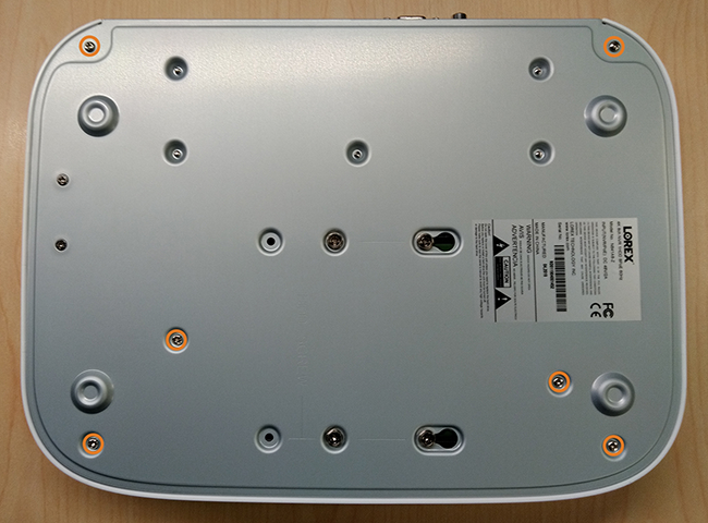
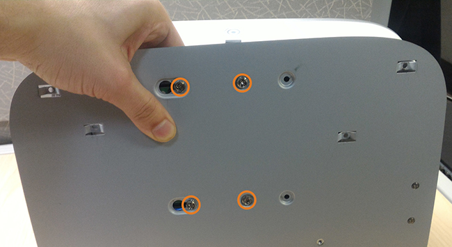
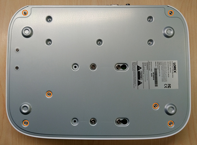
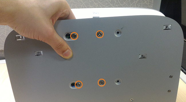
Step 2. Turn the recorder over, then remove the 6 bottom panel screws as shown in the image below.
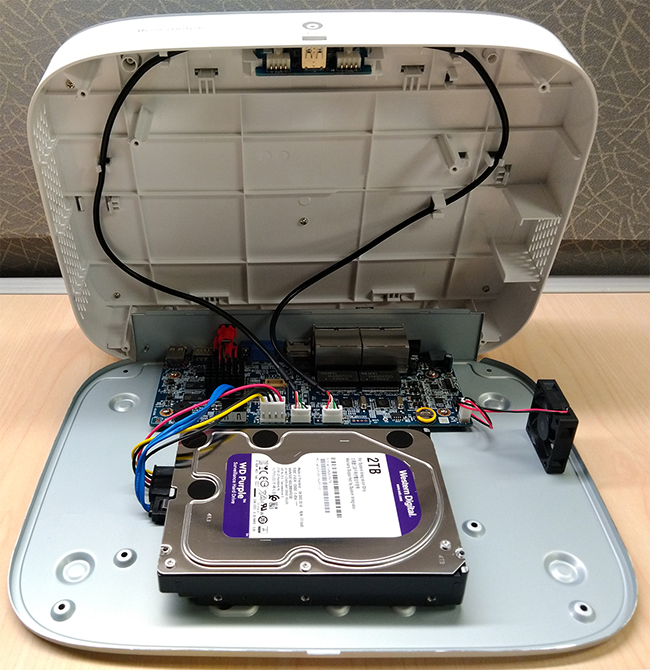
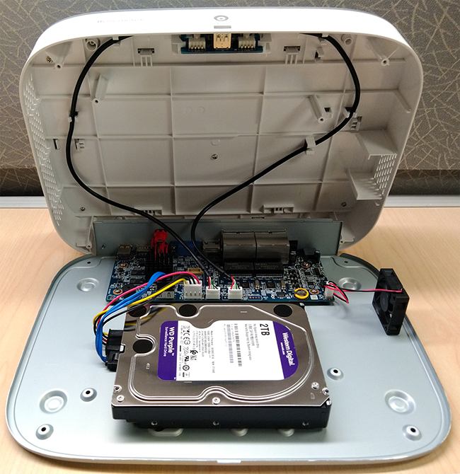
Step 3. Turn the recorder over carefully, then lift the top panel so you can access the hard drive.
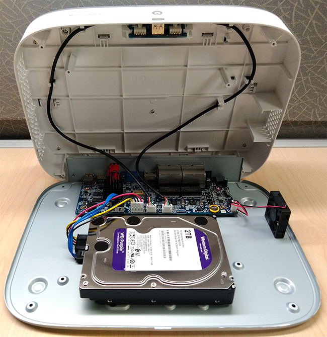
IMPORTANT: The wiring to the front panel button and USB port runs along the top panel of the recorder. When separating the top panel, rest it carefully beside the bottom panel as shown below.
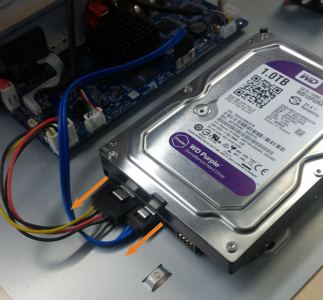
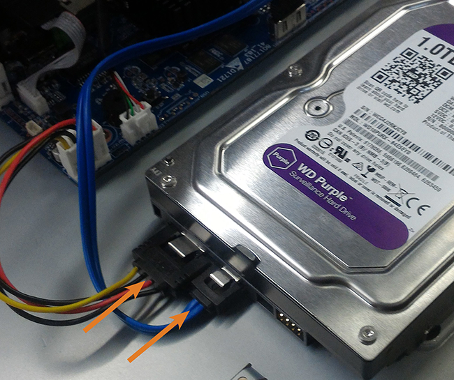
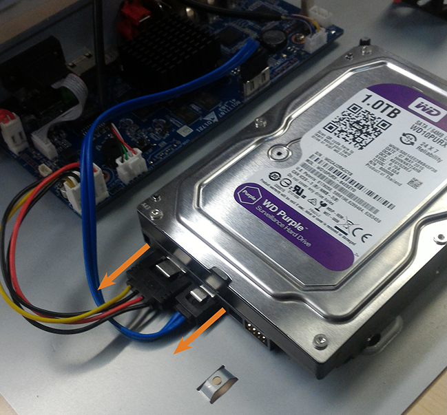
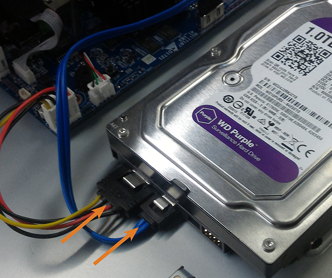
Step 4. Now carefully remove the power and SATA cables from the hard drive as shown below.
Step 5. Carefully pick up the hard drive to lift the bottom panel, being mindful of the sharp edges of the bottom panel. Remove the hard drive screws (4×) from the bottom panel. Hold onto the hard drive so it remains in place when all screws have been removed.
Step 6. If you are not immediately going to install a new hard drive, replace the top panel and the 6 bottom panel screws.
Installing a new hard drive
IMPORTANT: If you are replacing your hard drive, please note that you don’t need an extra SATA cable. Your recorder is already equipped with one SATA cable inside it which you can use for your new hard drive.
WARNING: Make sure that your recorder is OFF and the power adapter is disconnected before removing/installing a hard drive.
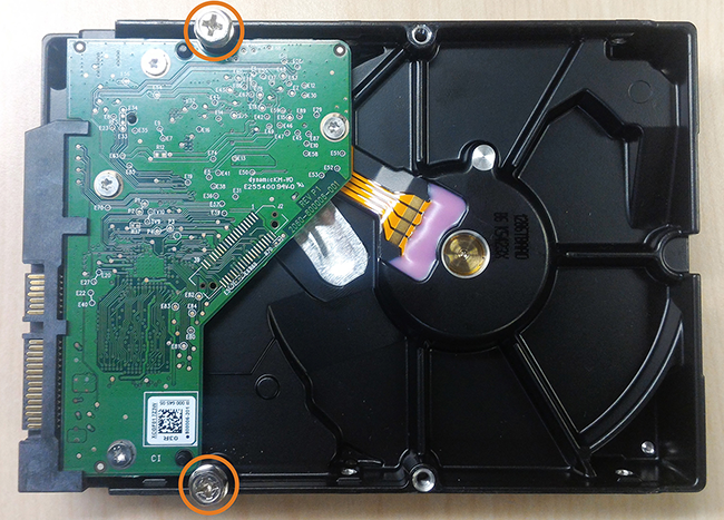
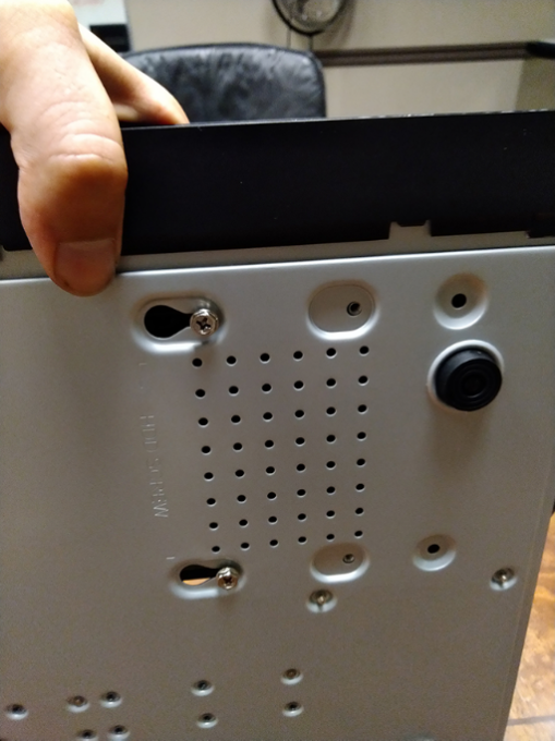
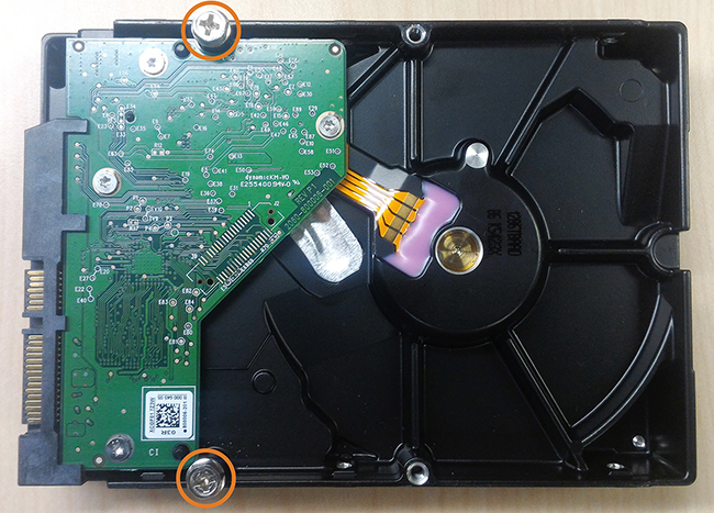
Step 1. Insert the 2 hard drive screws closest to the SATA and power ports on the hard drive and tighten them half way. See image below.
Step 2. Power off the system, and unplug all cabling from the system.
Step 3. Turn the recorder over, then remove the 6 bottom panel screws as indicated in the image below.
Step 4. Turn the recorder over carefully, then remove the top panel.
IMPORTANT: The wiring to the front panel button and USB port runs along the top panel of the recorder. When separating the top panel, rest it carefully beside the bottom panel as shown below.
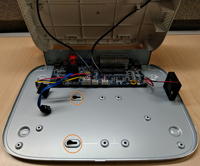
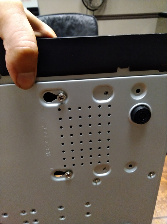
Step 5. Line the 2 half-inserted hard drive screws with the 2 holes shown in the image below.
Once you have inserted the hard drive screws to their respective slots, it should look like this.
Step 6. Carefully pick up the bottom panel with the hard drive, being mindful of the sharp edges of the bottom panel. Slide the 2 pre-inserted screws into the locked position, then tighten the screws. Insert and tighten the 2 remaining hard drive screws.
Step 7. Connect the power and SATA cables to the hard drive.
Step 8. Replace the top panel and the 6 bottom panel screws.
Section 2 – Replacing hard drive on older models
IMPORTANT: The instruction in this section is applicable to the following products (if you have a newer recorder, please go to Section 1 above):
Removing the hard drive
WARNING: Make sure that your recorder is OFF and the power adapter is disconnected before removing/installing a hard drive.
Step 1. Power off the system, and unplug all cabling from the system.
Step 2. Remove the back panel screws (4×). Remove the cover by sliding it backwards.
Step 3. Turn the recorder over carefully. Remove the 2 hard drive screws closest to the edge of the recorder. Loosen the remaining 2 hard drive screws, but do not remove them.
Step 4. Remove the power and SATA cables from the hard drive.
Step 5. Slide the hard drive out of the recorder.
Step 6. If you are not immediately going to install a new hard drive, replace the top panel and the 4 back panel screws.
Installing the hard drive
IMPORTANT: If you are replacing your hard drive, please note that you don’t need an extra SATA cable. Your recorder is already equipped with one SATA cable inside it which you can use for your new hard drive. If your recorder has two bays, you can install one more hard drive (for a total of two hard drives). When installing an additional hard drive, please note that the extra SATA cable is included in the accessory box.
WARNING: Make sure that your recorder is OFF and the power adapter is disconnected before removing/installing a hard drive.
Step 1. Insert the 2 hard drive screws closest to the SATA and power ports on the hard drive and tighten them half way.
Step 2. Power off the system, and unplug all cabling from the system.
Step 3. Remove the back panel screws (4×). Remove the cover by sliding it backwards.
Step 4. Insert the hard drive so the 2 pre-inserted screws line up with the holes in the bottom panel as shown below. Slide the hard drive in place. Insert the remaining 2 hard drive screws, and tighten all 4 screws tightly.
Step 5. Connect the power and SATA cables to the hard drive.
Step 6. Replace the top panel and the 4 back panel screws.
