Login
I am a happy user of this nice glasses, one day I did not manage to enter the DVR menu until I realized that the DVR module could not be activated using the button. The recording function seemed to be completely exhausted. However, a few days ago I was trying to upgrade the DVR firmware and therefore I saw that something went wrong and that it didn’t work is a correct assumption. The funny thing is, I just wanted to upgrade to have the option to turn on / off the sound in the menu, but I really didn’t want it because I had a microphone in the VTX or just off the audio channel if it’s static, the noise is annoying. I didn’t need it, I just wanted to have it so I made the device brick. But at this point, it was not possible to redo the upgrade using the SD card and solve the problem easily, so I was looking for another way to revive the device. Looking at the firmware binary, I discovered that the design of Chinese-made DVR devices should be very similar. The first hint was telling me that they were and that the firmware could be written directly into the flash chipKolinda of the RC Groups writings and then the Montis ” after a firmware update to Bruna each prodvr’y restore entitled” In the block we found a post. I discovered this information by scanning for strings that I saw in the firmware file CRESFW.BIN. As a result, the firmware of some other Chinese DVR devices is also distributed to the same filename and contains the same strings.
Finally, I learned to read and write a flash chip directly!
Good news; It is that the DVR in the Commander can be fixed after a failed upgrade attempt. The bad news is that it’s really not that bad, because if you’re in the RC hobby for a while, you must have been used to play with electronics – you have to separate the glasses and prepare the solder jumper wires on it. flash chip legs.
Things you will need:
- with relatively small tip soldering iron (I used TS100)
- thin jumper cables (I used them with dupont connectors )
- Flashrom utility program for reading / writing chip
- One of the programming devices listed on flashrom’s site
- stock firmware is kindly provided by Aomway (if you need the .BIN file from zip, it is 2097152 bytes long and different size firmware from any other official site or [running does not see the end of this article for some details]!)
- I assume you know how to solder and how to use basic tools such as solder, solder paste, pliers, screw driver set and multimeter
The Raspberry Pi I chose for the programmer was because there is one around me, and so it was clear. Using Pi is as convenient as it can run Linux, and doing advanced work tends to be easier only when using an advanced operating system.
Repair process
Then we have to separate the glasses. This must be clear. Remove the foam from the face plate and remove the small screw on the nose. Remove the face plate. There are two more screws remaining at the bottom of the glasses. Gently pull on the top and bottom parts as there are ribbon cables inside.
Now you need to set the flash chip. It is located on the top PCB with the top buttons. It has eight legs and a Winbond 25Q16CVNIG inscription . Here is a photo of him:
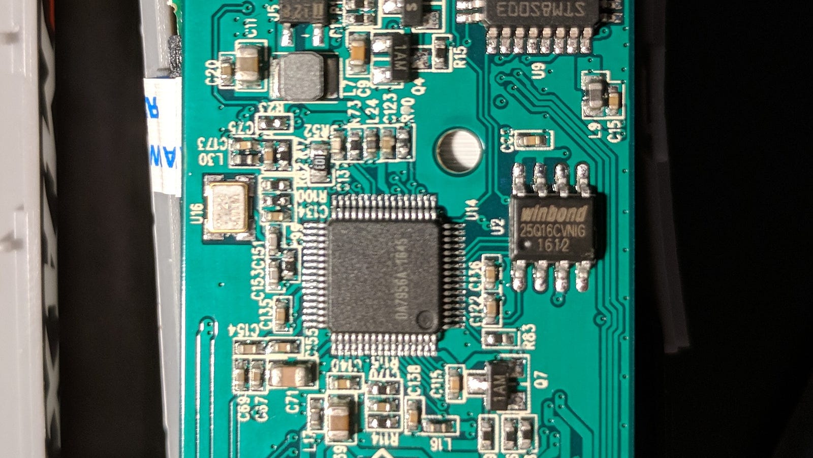
It is necessary to know the exact type of the chip to find the datasheet with the description of the functionality of the bipos (this quote on the datasheet can be seen below).
At this point, we need to prepare the Raspberry and tie it to the chip. Installing flashrom on a Debian-based Linux distribution is as easy as running the following command:
sudo apt-get install flashrom -y
If you are using another operating system, please see the flashrom’s documentation on how to install the executable file on your system. The subject flashromcommand is to run on the command line.
The way Pi is connected to the chip is described in the flashrom documentation . Here you can find a connection table showing which GPIO pin on the Pi goes to which month on the Winbond chip. It is very important to operate the chip from the 3.3V input (as shown correctly in the documentation) as overloading of the chip can easily kill it! Fortunately, Pi provides a very stable regulated 3.3V output, which makes this situation very comfortable. If you are going to use a flashing Arduino, you may need an additional component (such as a resistor) to get the correct output voltage.
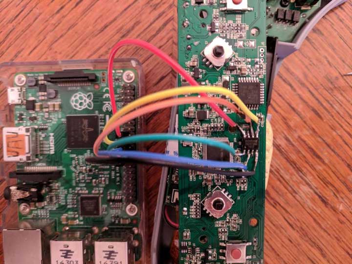
The picture below contains all the information necessary to make the connections between the chip and Pi. I was just putting the images together quickly, but there are things you need to know, not the lines that represent the cables. The only thing I did differently was not binding / HOLD and / WP VCC. I couldn’t get the flashrom to detect the chip that way. In some cases, it is also possible for the chip to be completely separated from the PCB during flash operation, or by removing the VCC leg from the rest of the PCB. In my case, none was required.
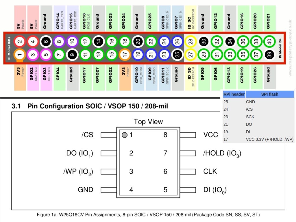
Note the point in the diagram to determine both the chip and the right direction. In real life all of the above looks like this:
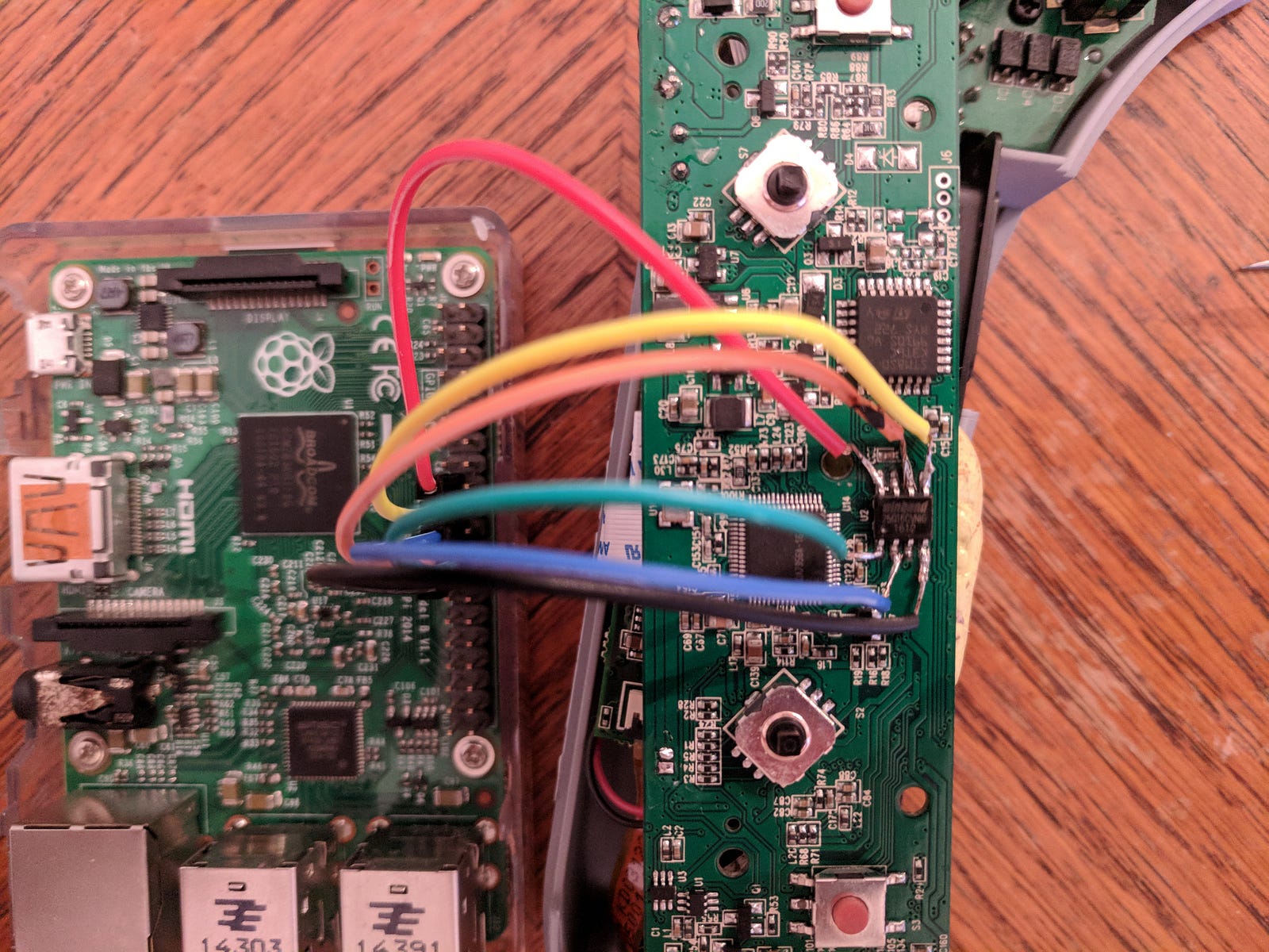
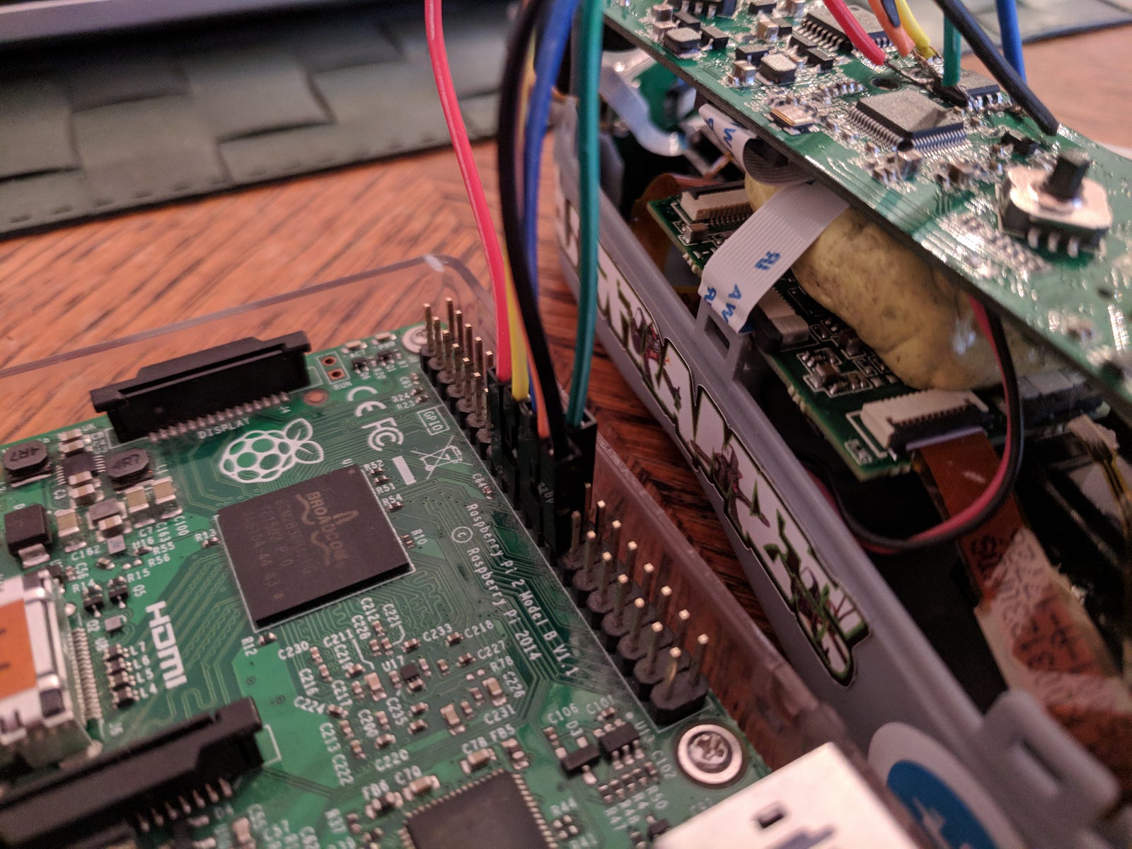
This may sound silly, but no device is supported while soldering it!
After completing the soldering process, it is a good idea to make sure that no shorts are available when using a multimeter in continuity mode. Because the chip’s legs are relatively small (although not as small as in other ICs), you may have mistakenly connected them with very large soldering solders.
If everything looks good, you can strengthen the Raspberry. Do not apply power to the glasses from their own strength during the flashing process. Use only 3.3V from Pi to power the circuit!
When pi is booted, the connection can be tested . Open a terminal, type it flashrom -p linux_spi:dev=/dev/spidev0.0and press enter. The Flashrom utility will try to detect the type of chip the programmer device is connected to. A similar output is expected:
Linux 4.9.41-v7 + (armv7l) flashrom on flashrom v0.9.9-r1954
it is free software, you can get the source code from https://flashrom.org .
Calibrating the delay cycle ... OK.
Winbond flash chip "W25Q16.V" (2048 kB, SPI) found on Linux_spi.
No action is specified.
If you receive an error message saying “No EEPROM / flash device found” , you need to check your cables and read the programmer-related documentation you selected on the flashrom website. This guide is not about meta-troubleshooting, it’s just an explanation of how I fix the unit and learn along the way.
Theoretically, if the current software on the chip is working and you want to change it for another reason (for example, to make a more upgraded update), it may be a good idea to make backups of the chips before writing to their content. In the current case, the firmware is bricked, but you can back up the firmware by giving this command from pure curiosity:
flashrom -p linux_spi:dev=/dev/spidev0.0 -c W25Q16.V -r backup.binIt recovers the contents of this chip from a file called backup.bin .
Now we can try to write the right software on the chip. To do this properly, the firmware binary is a total of 2097152 bytes in size (Winbond chip capacity). The firmware file in the Introduction section of this article is correct. Use the following command to write binary on the chip:
flashrom -p linux_spi:dev=/dev/spidev0.0 -c W25Q16.V -w MB01.This'sThe above MB01.BINis the firmware icon you downloaded, I have renamed it for convenience before.
The transaction must be completed successfully. Now you can test your glasses without cutting anything, just turn off the Raspberry and unplug the power cord, then power the glasses normally using the barrel connector. You need to enable DVR recording and enter the DVR menu. There will be a new option in the DVR menu to turn the sound on and off. At this point, you can wear your glasses and you’re done.
Why can’t you just use the upgrade firmware
Normally a firmware image should be the same size as the chip capacity it writes. By default, flashrom will complain, for example:
Error: Image size (1275738 B) does not match the size of the flash chip (2097152 B)!
W26Q16.V the capacity of the chip 2 Mb (or 16 Mbits) d . If you look at the size of the binary, aomway.com You can see that it is only 1.3 Mb. The reason behind this is that I assume that the normal upgrade process uses some kind of patching and that only chip parts are written. It is not known whether the binary is written as it is, a particular offset, divided into parts or written to different offsets in different parts. By examining my chip backup, I discovered that the binary file on the chip contains an upgrade non-binary 64-byte header and supports my assumption about this patch. Moreover, I tried to merge the upgrade binary into the backup binary that started after this header, but blinking the merged file did not make the device work. This says that the patch process may be more complex, but the exact patch method is still unknown.
You cannot write the upgrade software software on the chip, as it will not work. The binary you need is a full firmware image of a working pair of googles. I got this duo by contacting Sean on Aomway and I’m grateful to send the file I wanted for a day or so!
The morality of the story…
If everything goes well and you don’t need new features, upgrading the software is not a great idea.
Thank
I would like to thank these generous people for being very helpful and kindly embraced their knowledge! This made it possible to learn how to flash the chip from scratch until my device is fixed in a single day!
- Kolin ( kolins.cz )
- Multirotor Guide at Montis
References
- Stock Aomway Commander firmware binary (v1.2)
- Winbond W25Q16CVNIG datasheet
- Flashrom documentation on flashing using RaspberryPi
- manual flashrom
Seems complicated as he’ll trying to buy that.
i am not accessible on rstp and not recognized sd card. I’ve try multiple sd card but option formatting on app isn’t disponible, how do resolve this?i am not accessible on rstp and not recognized sd card. I’ve try multiple sd card but option formatting on app isn’t disponible, how do resolve this?
i am not accessible on rstp and not recognized sd card. I’ve try multiple sd card but option formatting on app isn’t disponible, how do resolve this?i am not accessible on rstp and not recognized sd card. I’ve try multiple sd card but option formatting on app isn’t disponible, how do resolve this?
very informative and revealing bravo!
very informative and revealing bravo!
great site man thank you
every post is very informative for your health ..
every post is very informative for your health ..
great site man thank you
very informative and revealing bravo!
These are all utterly hideous.
These are amazing. Thank you so much for sharing 🙂
every post is very informative for your health ..
These are amazing. Thank you so much for sharing 🙂
very informative and revealing bravo!
great site man thank you
please help me, my problem is not solved.
great site man thank you
very informative and revealing bravo!
great site man thank you
I did all but it does not
great site man thank you
These are amazing. Thank you so much for sharing 🙂
I wonder if I can give you my e-mail address.
I did all but it does not