CP Plus 4K AI NVR Full Guide, The CP Plus Pro Series of NVRs have been meticulously
designed for providing you with upgraded performance
and higher recording quality in your IP video
surveillance solution.
The robust processor that has
been inculcated in this NVR lets you enjoy 4K resolution
and brings out every little detail from the picture
in a clear view. This NVR is being used worldwide at a
variety of places because of its easy-to-install design.
This NVR also supports the features of open architecture
that enable multi-user access and is also compatible
with ONVIF 2.4 protocol which makes it interoperable
with 4K cameras.
CP Plus 4K AI NVR Full Guide
Read Next :
- EasyVMS P6SLite PC Software Manual
- Wireless NVR Kit Setup Guide
- Upgrading Firmware for a Legacy VMAX DVR
This series NVR is a high-performance network video recorder. This series product support local preview, multiple-window display, recorded file local storage, remote control and mouse shortcut menu operation, and remote management and control function.
This series product supports center storage, front-end storage and client-end storage. The monitor zone in the front-end can be set in anywhere. Working with other front-end devices such as IPC, NVS, this series product can establish a strong surveillance network via the CMS. In the network system, there is only one network cable from the monitor center to the monitor zone in the whole network. There is no audio/video cable from the monitor center to the monitor zone. The whole project is featuring of simple connection, low-cost, low maintenance work.
This series NVR can be widely used in many areas such as public security, water conservancy, transportation and education.
| Cloud
Upgrade |
• For the NVR connected with the Internet, it supports online upgrade to update applications. |
| Real-time
Surveillance |
surveillance.
|
| Playback |
|
| User
Management |
|
| Storage |
|
![]()
Slight difference may be found on the user interface. The following figures for reference only.
This chapter introduces device initial settings such as boot up, device initialization, reset password, and quick settings.

For device security, connect the NVR to the power adapter first and then connect the device to the power socket. The rated input voltage matches the device power button. Make sure the power wire connection is OK. Then click the power button Always use the stable current, if necessary, UPS is a best alternative measure.
Step 1 Connect the device to the monitor and then connect a mouse.
Step 2 Connect power cable.
Step 3 Click the power button at the front or rear panel and then boot up the device. After device booted up, the system is in multiple-channel display mode by default.
If it is your first time to use the device, set a login password of admin (system default user). You can select to use unlock pattern to login or not at your own choosing.
![]()
For your device safety, keep your login password of admin well after the initialization steps, and change the password regularly.
Step 1 Boot up NVR.
The Device Initialization interface is displayed. See Figure 2.1.
Figure 2.1
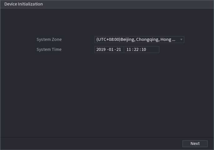
Step 2 Set system time zone according to the actual environment.
![]()
Click to
shut down the device. It is suitable for the system integrator or the user to shut
down directly after setting the time zone
Step 3 Click Next.
The Device Initialization interface is displayed. See Figure 2.2.
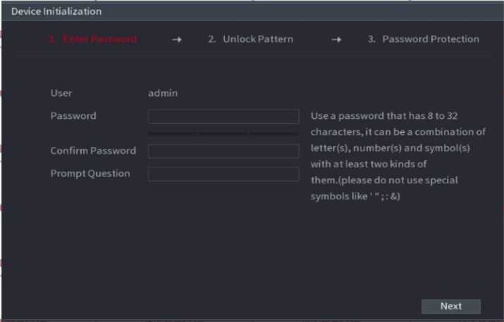
Step 4 Set login password of admin.
| Parameter | Description |
| User | By default, the user is admin. |
| Password | In the Password box, enter the password for admin.
The new password can be set from 8 characters through 32 characters and contains at least two types from number, letter and special characters (excluding , , “;”, “:” and “&”). |
| Confirm Password | |
| Prompt Question | In the Prompt Question box, enter the information that can remind you of the password.
On the login interface, click , the prompt will display to help you reset the password. |
For your device own safety, create a strong password of your own choosing. We also recommend you change your password periodically especially in the high security system.
Step 5 Click Next.
The Unlock Pattern interface is displayed. See Figure 2.3.
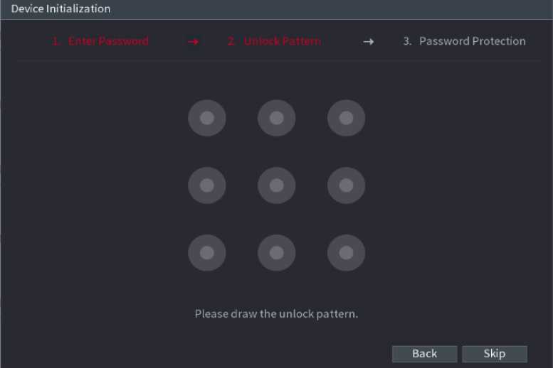
Figure 2.3
After set unlock pattern, the Password Protection interface is displayed. See Figu re 2.4.
The pattern that you want to set must cross at least four grids. If you do not want to configure the unlock pattern, click Skip. Once you have configured the unlock pattern, the system will require the unlock pattern as the default login method. If you skip this setting, enter the password for login.
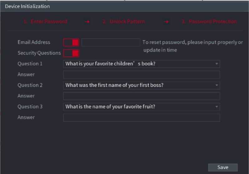
Figure 2.4
Step 7 Set security questions.
After configuration, if you forgot the password for admin user, you can reset the password through the reserved email address or security questions. If you do not want to configure the settings, disable the email address and security questions functions on the interface.
| Password Protection Mode | Description |
| Email Address | Enter the reserved email address.
In the Email Address box, enter an email address for password reset. If you forget the password, enter the security code that you will get from this reserved email address to reset the password of admin. |
| Security
Questions |
Configure the security questions and answers.
If you forget the password, enter the answers to the questions can allow you to reset the password. |
Step 8 Click Save to complete the device initialization setup.
Step 9 Device goes to startup wizard interface.
You can reset the password by the following methods when you forgot the password for admin account. If the password reset function is enabled, you can use mobile phone to scan the QR code to reset the password.
If the password reset function is disabled, there are two situations:
o If you configured security questions, you can reset the password by the security questions.
o If you did not configure the security questions, you can only use the reset button on the mainboard to restore
the Device to factory default.
Reset button is for some series product only.
After enabling password reset function, you can scan QR code on the local menu to reset password.
Step 1 Select Main Menu ^ Account ^ Reset Password.
The Reset Password interface is displayed. See Figure 2.5
Reset Password
Enable
Email Address
Secu rity Question
Please set a security question so that you can find the password of admin again.
Question 1 What is your favoritechildren’s book?
Answer
Question 2 What was the first name of your first boss?
Answer
Question 3 What is the name of your favorite fruit?
Answer
Apply Cancel
Figure 2.5
Step 2 Check the box to enable reset function.
![]()
This function is enabled by default.
Step 3 Click Apply to set settings.
If the password reset function is disabled, you can follow the ways listed below to reset password.
Device supports Reset button on the main board: You can answer the security question on the local menu or click the Reset button on the main board to reset password.
• Device does not support Reset button on the main board: You can only answer the security question on the local menu to reset password. (Make sure you have set security questions).
Step 1 Enter the SYSTEM LOGIN interface.
- If you have configured unlock pattern, the unlock pattern login interface is displayed.
- See Figure 2.6. Click Forgot Pattern, the password login interface is displayed. See Figure 2.7.
- If you did not configure unlock pattern, the System Login interface is displayed. See Figure 2.7.
![]()
To login from other user account, on the unlock pattern login interface, click Switch User, or on the password login interface, in the Switch User list, select another user to login.
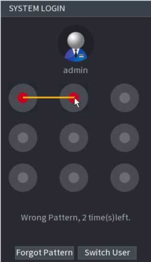
Figure 2.6
r
u
User Name admin
OK Cancel
Figure 2.7
Step 2 Click
- If you have set the reserved email address, the Prompt interface is displayed. See Figure 2.8.
- If you did not set the reserved email address, the email entering interface is displayed. See Figure 2.9.
- Enter the email address, and then click Next, the Prompt message interface is displayed. See Figure 2.8.
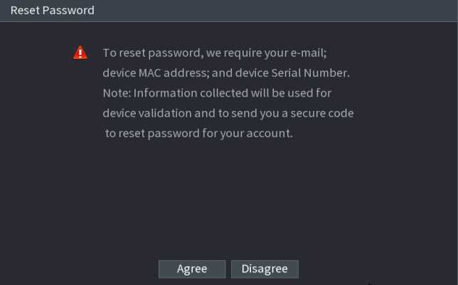
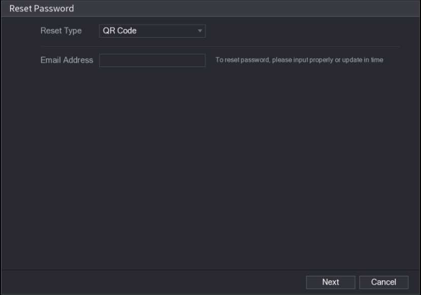
Figure 2.9
Step3 Click Next.
The Reset Password interface is displayed. See Figure 2.10.
After clicking Next, the system will collect your information for password reset, purpose and the information includes
not limited to email address, MAC address, and device serial number. Read the prompt carefully before clicking N
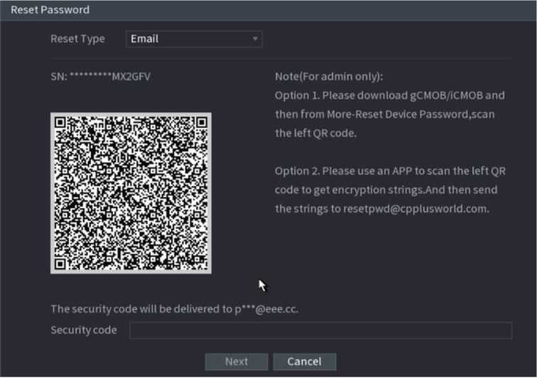
Figure 2.10
Step 4 Reset the password.
 QR code – Follow the onscreen instructions to get the security code in your reserved email address. In the Security code box, enter the security code.
You can get the security code twice by scanning the same QR code. If you need to get the security code once again, refresh the interface.
Use the security code received in your email box to reset the password within 24 hours; otherwise the security code becomes invalid.
- Security questions
On the Reset password i nterface as shown i n Figu re 2 . 11, i n the Reset Type l ist, select Security Questions, the Security Questions interface is displayed.
If you did not configure the security questions before, in the Reset Type list, there is no Security Questions.
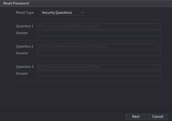
Figure 2.11
The Reset Password interface is displayed. See Figure 2.12.
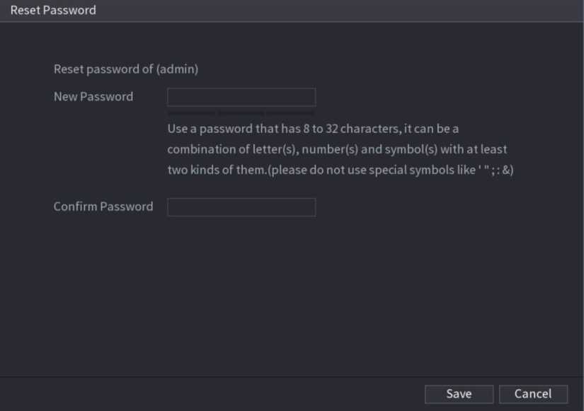
Figure 2.12
Step 6 In the New Password box, enter the new password and enter it again in the Confirm Password box.
Step 7 Click Save. The password resetting is complete.
A pop-up message is displayed asking if you want to sync the password with the remote devices. See Figure 2.13.
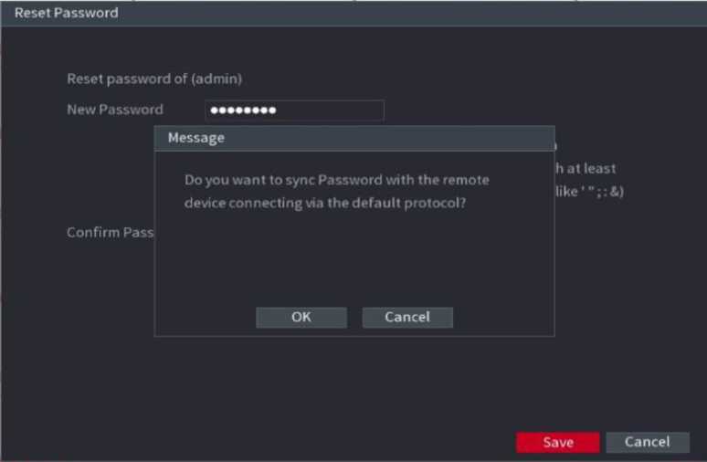
Figure 2.13
You can always use the reset button on the mainboard to reset the Device to the factory default settings.
Reset button is for some series products only.
Step 1 Disconnect the Device from power source, and then remove the cover panel. For details about removing the cover panel, see “3.4 HDD Installation.”
Step 2 Find the reset button on the mainboard, and then connect the Device to the power source again.
Step 3 Press and hold the reset button for 5 seconds to 10 seconds. See Figure 2.14 for the location of the reset button.
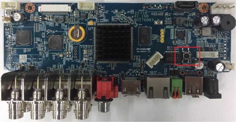
Step 4 Reboot the Device.
After the Device is rebooted, the settings have been restored to the factory default. You can start resetting the password.
After you successfully initialized the device, it goes to startup wizard. Here you can quickly configure your device. Click Next, device goes to General interface.
The startup wizard interface only displays after you first login the device and have set the admin password. See Figure 2.15.
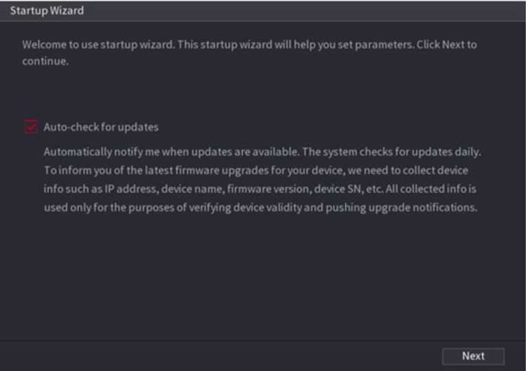
Figure 2.15
If you select the Auto-check for updates check box, the system will notify you automatically when updates are available. After the auto-check function is enabled, to notify you to update timely, the system will collect the information such as IP address, device name, firmware version, and device serial number. The collected information is only used to verify the legality of the Device and push upgrade notices.
If you cancel the Auto-check for updates check box, the system will not perform automatic checks.
You can set NVR basic information such as system date, holiday etc. You can also configure general settings by selecting Main Menu ^ SYSTEM ^ General.
You can set device basic information such as device name, serial number.
Step 1 Click Next.
The General interface is displayed. See Figure 2.16.
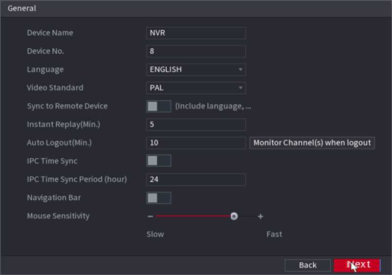
Figure 2.16
| Parameter | Description |
| Device Name | In the Device Name box, enter the Device name. |
| Device No. | In the Device No. box, enter a number for the Device. |
| Language | In the Language list, select a language for the Device system. |
| Video Standard | In the Video Standard list, select PAL or NTSC according to your actual situation. |
| Sync to Remote
Device |
Enable this function; the NVR can synchronize information with the remote device such as Language, video standard, time zone. |
| Instant Play (Min.) | In the Instant Play box, enter the time length for playing back the recorded video. The value ranges from 5 to 60.
On the live view control bar, click the instant playback button to play back the recorded video within the configured time. |
| Auto Logout (Min.) | In the Auto Logout box, enter the standby time for the Device. The Device automatically logs out when it is not working for the configured time period. You need to login the Device again.
The value ranges from 0 to 60. 0 indicates there is not standby time for the Device. Click Monitor Channel(s) when logout. You can select the channels that you want to continue monitoring when you logged out. |
| IPC Time Sync | Syncs the Device time with IP camera. |
| Parameter | Description |
| IPC Time Sync
Period (hour) |
In the IPC Time Sync Period box, enter the interval for time sync. |
| Auto logout | You can set auto logout interval once login user remains inactive for a specified time. Value ranges from 0 to 60 minutes. |
| Navigation Bar | Enable the navigation bar. When you click on the live view screen, the navigation bar is displayed. |
| Mouse Sensitivity | Adjust the speed of double-click by moving the slider. The bigger the value is, the faster the speed is. |
Step 3 Click Next button to save settings.
You can set device time. You can enable NTP (Network Time Protocol) function so that the device can sync time with the NTP server.
You can also configure date and time settings by selecting Main Menu ^ SYSTEM ^ GENERAL ^ Date & Time.
Step 1 Click Date & Tim tab. See Figure 2.17.
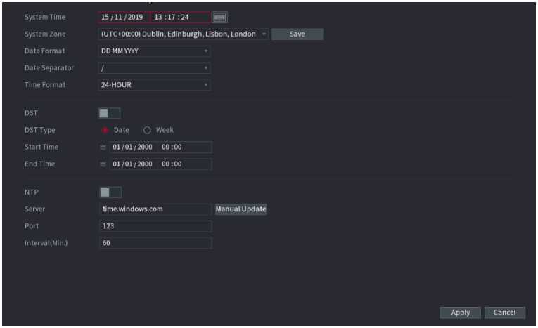
Figure 2.17
Step 2 Configure the settings for date and time parameters.
| Parameter | Description |
| System Time | In the System Time box, enter time for the system. Click the time zone list, you can select a time zone for the system, and the time in adjust automatically.
/f\ |
| Do not change the system time randomly; otherwise the recorded video cannot be searched. It is recommended to avoid the recording period or stop recording first before you change the | |
| system time. | |
| System Zone | In the System Zone list, select a time zone for the system. |
| Date Format | In the Date Format list, select a date format for the system. |
| Date Separator | In the Date Separator list, select a separator style for the date. |
| Time Format | In the Time Format list, select 12-HOUR or 24-HOUR for the time display style. |
| DST | Enable the Daylight-Saving Time function. Click Week or click Date. |
| Start Time | Configure the start time and end time for the DST. |
| End Time | |
| NTP | Enable the NTP function to sync the Device time with the NTP server. |
| Server | In the Server box, enter the IP address or domain name of the corresponding NTP server.
Click Manual Update, the Device starts syncing with the server immediately. |
| Port | The system supports TCP protocol only and the default setting is 123. |
| Interval (Min.) | In the Interval box, enter the amount of time that you want the Device to sync time with the NTP server. The value ranges from 0 to 65535. |
Step 3 Click Next button to save settings.
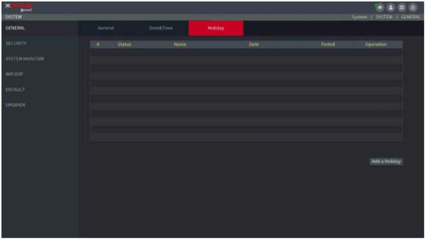
Here you can add, edit, delete holiday. After you successfully set holiday information, you can view holiday item on the record and snapshot period.
You can also configure holiday settings by selecting Main Menu ^ SYSTEM ^ GENERAL ^ Holiday.
Step1 Click Next.
The Holiday interface is displayed. See Figure 2.18.
Figure 2.18
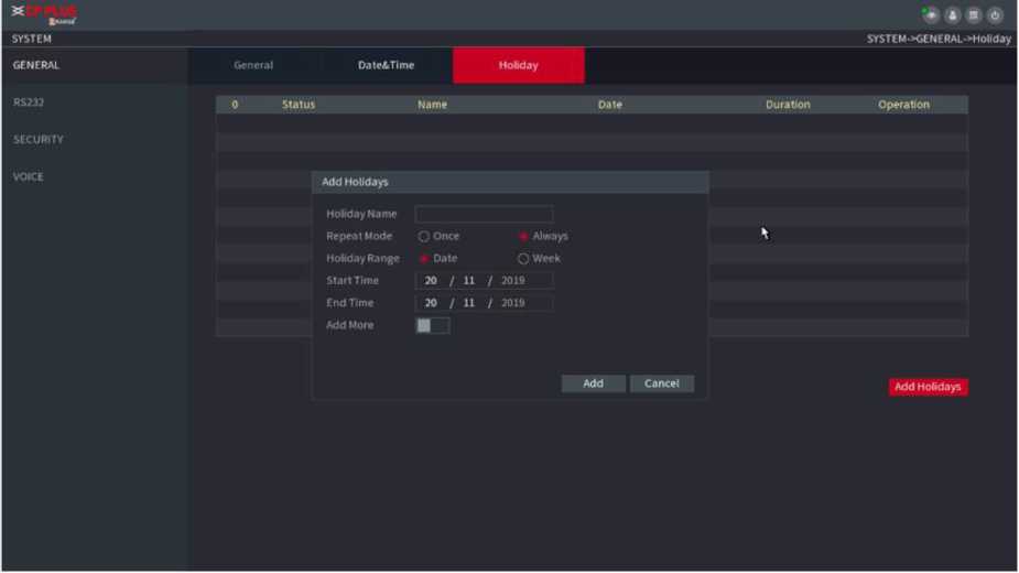
Step2 Click Add Holidays button, the Add Holidays interface is displayed. See Figure 2.19.
Figure 2.19
Step 3 Set holiday name repeat mode and holiday mode.
Click Add more to add new holiday information.
Step 4 Click Add button, you can add current holiday to the list.
• Click the dropdown list of the state; you can enable/disable holiday date.


to change the holiday information. Click
to delete current date.
Step 5 Click Next button to save settings.
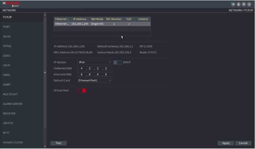
You can set device IP address, DNS (Domain Name System) information. You can also configure basic network settings by selecting Main Menu ^ NETWORK ^ TCP/IP.
Make sure the device has properly connected to the network.
Step 1 Click Next.
![]()
![]()
The TCP/IP interface is displayed. See Figure 2.20.
Different series products have different Ethernet adopter amount and type. Refer to the actual product.
Figure 2.20
The Edit interface is displayed. See Figure 2.21.
| Parameter | Description |
either of which you can request the Device to provide the services such as HTTP and RTSP. You need to configure a default Ethernet port (usually the Ethernet port 1 by default) to request the services from the device end such as DHCP, Email and FTP. If one of the two Ethernet ports is disconnected as detected by networking testing, the system network status is regarded as offline.
|
|
| Net Mode | Normally only one Ethernet port is working and when this port fails, the other port will start working automatically to ensure the network connection.
When testing the network status, the network is regarded as offline only when both of the two Ethernet ports are disconnected. The two Ethernet ports are used under the same LAN. • Load Balance: Two network cards share one IP address and they are working at the same time to share the network load averagely. If one of them fails, the other can continue working normally. When testing the network status, the network is regarded as offline only when both of the two Ethernet ports are disconnected. The two Ethernet ports are used under the same LAN. |
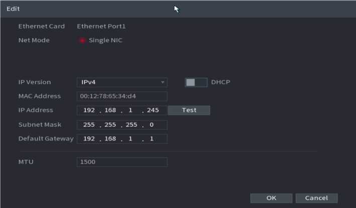
Figure 2.21
In the Ethernet Card list, select an Ethernet port as a default port. Th is setti ng is available on ly wh en t he M ulti-address is selected in the Net Mode list.
Default Ethernet Port
| Parameter | Description |
| IP Version | In the IP Version list, you can select IPv4 or IPv6. Both versions are supported for access. |
| MAC Address | Displays the MAC address of the Device. |
| DHCP | Enable the DHCP function. The IP address, subnet mask and default gateway are not available for configuration once DHCP is enabled.
If DHCP is effective, the obtained information will display in the IP Address box, Subnet Mask box and Default Gateway box. If not, all values show 0.0.0.0. If you want manually to configure the IP information, disable the DHCP function first. If PPPoE connection is successful, the IP address, subnet mask, default gateway, and DHCP are not available for configuration. |
| IP Address | Enter the IP address and configure the corresponding subnet mask and default gateway.
IP address and default gateway must be in the same network segment. |
| Subnet Mask | |
| Default Gateway | |
| DNS DHCP | Enable the DHCP function to get the DNS address from router. |
| Preferred DNS | In the Preferred DNS box, enter the IP address of DNS. |
| Alternate DNS | In the Alternate DNS box, enter the IP address of alternate DNS. |
| MTU | In the MTU box, enter a value for network card. The value ranges from 1280 byte through 1500 byte. The default is 1500. |
| Test | Click Test to test if the entered IP address and gateway are interworking. |
Step 4 Click OK to NIC settings.
Device goes back to TCP/IP interface.
Step 5 Set network parameters.
| Parameter | Description |
| IP Version | There are two options: IPv4 and IPv6. Right now, system supports these two IP address formats and you can access via them. |
| Preferred DNS server | DNS server IP address. |
| Alternate DNS server | DNS server alternate address. |
| MAC Address | Displays the MAC address of the Device. |
| DHCP | Enable the DHCP function. The IP address, subnet mask and default gateway are not available for configuration once DHCP is enabled.
If DHCP is effective, the obtained information will display in the IP Address box, Subnet Mask box and Default Gateway box. If not, all values show 0.0.0.0. If you want manually to configure the IP information, disable the DHCP function first. If PPPoE connection is successful, the IP address, subnet mask, default gateway, and DHCP are not available for configuration. |
| LAN download | System can process the downloaded data first if you enable this function. The download speed is 1.5X or 2.0X of the normal speed.
For IPv6 version, the IP address, default gateway, preferred DNS; alternate DNS is 128-digit. Fill in all items here. This function is for some series product only. |
Parameter
Description
Step 6 Click Next to complete the settings.
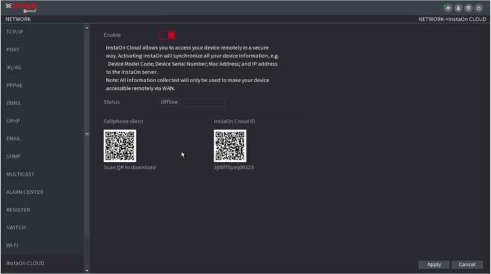
Scan the QR code, download the App to the cell phone, you can use the smart phone to add the device.
- Scan the QR code on the actual interface to download the cell phone app. Register an account and then use.
- Go to the http://orange.instaon.com/ to register an account and use the SN to add a device. Refer to the INSTAON operation manual for detailed information.

Before use the INSTAON function, make sure the NVR has connected to the WAN.
Step 1 Click Next button.
The INSTAON interface is displayed. See Figure 2.22.
Select Main Menu ^ Network ^ INSTAON, you can go to INSTAON interface too.
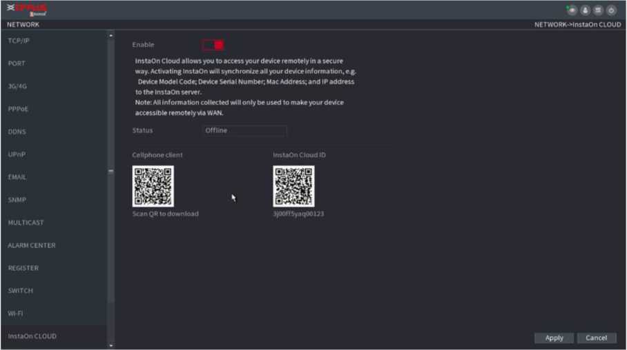
Figure 2.22
Step 2 Check the box to enable INSTAON function.
![]()
After the INSTAON function is enabled and connected to the Internet, the system will collect your information for remote access, and the information includes but not limited to email address, MAC address, and device serial number.
Step 3 Click Next button to complete setup.
The status is online if the INSTAON registration is successful.
![]() Step 1 Use your cell phone to scan the QR code under Cell Phone Client to download the application.
Step 1 Use your cell phone to scan the QR code under Cell Phone Client to download the application.
Step 2 On your cell phone, open the application, and then tap
Step 3 The menu is displayed. You can start adding the device.
The Device Manager interface is displayed. See Figure 2.23.
![]()
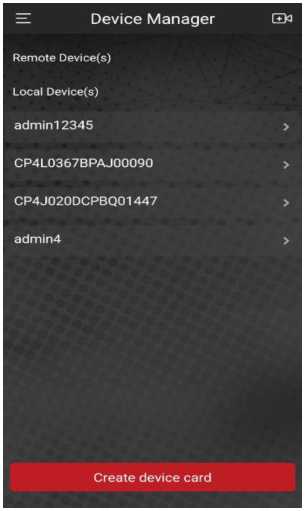
> Tap
Figure 2.23
on the top right corner.
The i nte rfa ce re q u i ri ng d evi ce initialization is displayed. A pop-up message reminding you to make sure the Device is initialized is displayed.
- Tap OK.
- If the Device has not been initialized, Tap Device Initialization to perform initializing by following the onscreen instructions.
- If the Device has been initialized, you can start adding it directly.
> Tap Add Device.
The Add Device interface is displayed. See Figure 2.24.
![]()
You can add wireless device or wired device. The Manual takes adding wired device as an example.
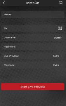
Figure 2.24
- Tap INSTAON.
The INSTAON interface is displayed. See Figure 2.25.
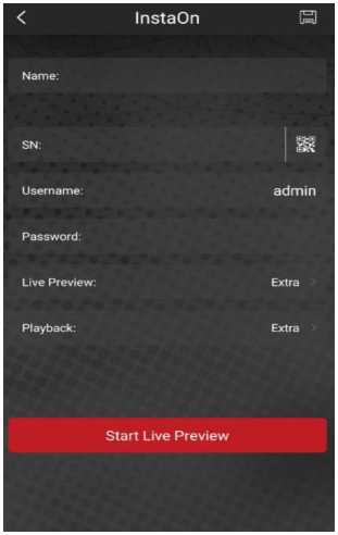
Figure 2.25
Enter a name for the NVR, the username and password, scan the QR code under Device SN.
- Tap Start Live P review.
The Device is added and displayed on the live view interface of the cell phone. See Figure 2.26.
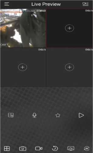
Figure 2.26
If you do not select Smart add function during the initialization process, go to the remote Device interface to register a remote device.
After adding remote device, the device can receive, store, and manage the video streams of the remote device. You can view, browse, play back and manage several remote devices at the same time.
Step 1 On the INSTAON interface, click Next button.
The REGISTRATION interface is displayed. See Figure 2.27.
![]()
There are two ways to go to Registration interface.
- Select Main Menu ^ CAMERA ^ REGISTRATION ^ Camera Registration, you can go to the Camera Registration interface.
- On the preview interface, right click mouse and then select Camera Registration.
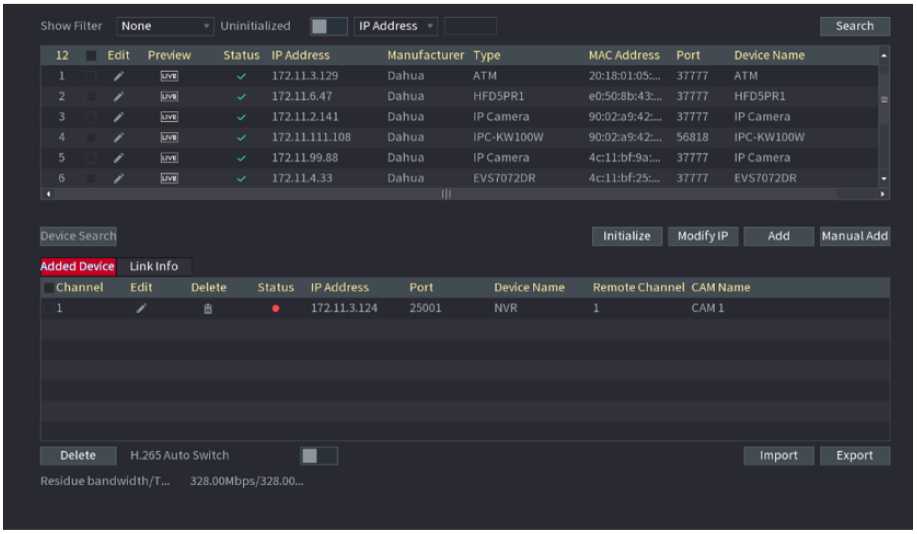
Figure 2.27
Step 2 Register remote device.
- Search and then add
- Click Device Search.
System displays searched devices at the upper pane.
- Double-click a remote device or select a remote device and then click Add to register it to the Added Device
list. See Figure 2.28.
The search results do not display the remote camera that has registered to the system.
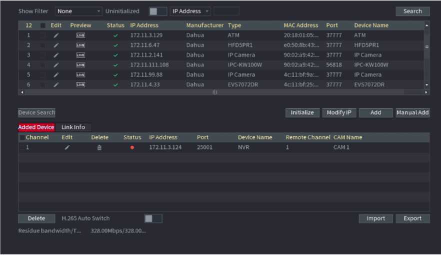
Figure 2.28
| Add | In the Searched Device List area, select the device that you want to add. |
| Manual Add | Add the device by manually configuring settings such as IP address, channel selection. |
| Added Device List | Displays the added devices. You can edit and delete the device and view the device information. |
| Delete | Select the check box of the added device, and then click Delete to delete the added device. |
| Import | Select the searched devices and then click Import to import the devices in batches. |
| Export | Select the added devices and then click Export. The exported devices information is saved into the USB storage device. |
- Manual Add
- Click Manual Add.
The Manual Add interface is displayed. See Figure 2.29.
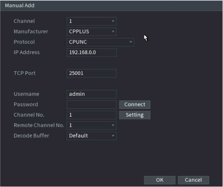
Configure parameters.
| Parameter | Description |
| Channel | In the Channel list, select the channel that you want use on the Device to connect the remote device. |
| Manufacturer | In the Manufacture list, select the manufacturer of the remote device. |
| IP Address | In the IP Address box, enter the IP address of remote device.
The default is 192.168.1.245 which the system cannot connect to. |
| RTSP Port | The default value setting is 554. You can enter the value according to your actual situation. |
| HTTP Port | The default value setting is 80. You can enter the value according to your actual situation.
If you enter other value, for example, 70, and then you should enter 70 after the IP address when logging in the Device by browser. |
| Username | Enter the username of the remote device. |
| Password | Enter the password of the user for the remote device. |
| Remote Channel | Enter the remote channel number of the remote device that you want to add. |
| Decoder Buffer | In the Decoder Buffer list, select Default, Realtime, or Fluent. |
| Protocol Type | If the remote device is added through private protocol, the default type is TCP.
If the remote device is added through Onvif protocol, the system supports Auto, TCP, UDP, or MULTICAST. If the remote device is added through other manufacturers, the system supports TCP and UDP. |
| Encrypt | If the remote device is added through Onvif protocol, selecting the Encrypt check box will provide encryption protection to the data being transmitted.
To use this function, the HTTPS function should be enabled for the remote IP camera. |
• Click OK.
The remote device information is displayed on the Added Device list.
Step 4 Click Next to complete the remote device registration.


Click
to change the remote device information. Click
to delete remote device.
Once the multiple-sensor device has registered to the device system displays the channel status on the Link info. See Figure 2.30. It shows one remote device has occupied two channels: D1, D3.
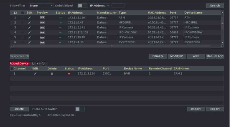
Figure 2.30
After set record schedule and snapshot schedule, the device can automatically record video and snapshot image at the specified time. Select Main menu ^ STORAGE ^ SCHEDULE, you can go to the SCHEDULE interface.
After set schedule record, device can record video file according to the period you set here. For example, the alarm record period is from 6:00-18:00 Monday, device can record alarm video files during the 6:00-18:00.
All channels are record continuously by default. You can set customized record period and record type.
Step 1 Click Next button.
The Rec interface is displayed. See Figure 2.31.
Channel
Pre-record
□ Saturday
s Redundancy
E POS
Regular
MD
Alarm
MD&Alarm
IVS
□ Sunday
©
O Monday
O
□ Tuesday
©
o Wednes…
»
□ Thursday
©
q Friday
©
Default
Copy
Apply
Step 2 Select a channel from the dropdown list, you can set different record plans for different channels. Select All if you want to set for all channels.
| Parameter | Description |
| Channel | In the Channel list, select a channel to record the video. |
| Pre-record | In the Pre-record list, enter the amount of time that you want to start the recording in advance. |
| Redundancy | If there are several HDDs installed to the Device, you can set one of the HDDs as the redundant HDD to save the recorded files into different HDDs. In case one of the HDDs is damaged, you can find the backup in the other HDD.
Select Main Menu > STORAGE > HDD MANAGER, and then set a HDD as redundant HDD. Select Main Menu ^ STORAGE ^ SCHEDUE ^ Record, and then select the Redundancy check box.
This function is for some series products only. The redundant HDD only back up the recorded videos but not snapshots. |
| ANR | You can set ANR (auto network resume) function.
The IPC continues record once the NVR and IPC connection fails. After the network becomes normal, the NVR can download record file during the offline period from the IPC. It is to guarantee there is no record loss on current connected IPC channel. Set the max. record upload period. Once the offline period is longer than the period you set here, IPC can only upload the record file during the specified period. This function is for IPC that installed SD card and the record function is enabled. |
| Period | Define a period during which the configured recording setting is active. See Figure 2.32.
The system only activates the alarm in the defined period. |
| Copy | Click Copy to copy the settings to other channels. |
Period
Current Date: Sunday
| Period 1 | 00 : | 00 – | 24 : | 00 | Regular | MD | Alarm | MD&Ata rm | □ IVS | □ POS |
| Period 2 | 00 : | 00 | 24 : | 00 | □ Regular | □ MD | Alarm □ | MD&Alarm | □ ivs | □ POS |
| Period 3 | 00 : | 00 – | 24 : | 00 | □ Regular | □ MD | Alarm | MD&Alarm | □ IVS | □ POS |
| Period 4 | 00 : | 00 – | 24 : | 00 | □ Regular | □ MD | Alarm | MD&Alarm | □ IVS | □ POS |
| Period 5 | 00 : | 00 – | 24 : | 00 | □ Regular | □ MD | Alarm | MDtAlarm | □ IVS | □ POS |
| Period 6
Copy □ All Sunday |
00 : | 00 –
Monday |
24 : | 00
21 Tuesday |
□ Regular
F Wednes… |
□ MD
F Thursday |
Alarm
C Friday |
MD&Alarm
1 | Satu |
□ IVS
rday |
□ POS |
OK Cancel
Step 3 Set record type. See Figure 2.34.
□ AU
Q Regular ■ MD
■ Alarm ■ MD&Alarm ■ IVS ■ POS
- When the record type is MD (motion detect), alarm, MD & Alarm, IVS and POS, enable the channel record function when corresponding alarm occurs. For example, when the alarm type is MD, select Main Menu ^ ALARM ^ VIDEO DETECTION ^ Motion Detect, select the record channel and enable record function. See Figure 2.34
- When the record type is MD (motion detect), alarm, MD & Alarm, IVS and POS.
| Charnel
Enable |
1
■ |
Region sensitivity | Seiling
3 |
|
| Period | Setting | Anti-Dither | 5 | s |
| Alarm Out
[ | Show Message Record Channel |
Setting
I Alarm Upload Setting |
Latch
| Send Email |
10 | s |
| [1 PTZ Activation | Setting | Post-Record | 10 | s |
| [ I Tour
[ | Buzier | Voice Prompts |
Setting
Log None |
| PictureStora | ee |
Default copy Refresh
Apply cancel
Figure 2.34
Step 4 Set record period. It includes edit mode and draw mode. See Figure 2.35.
If you have added a holiday, you can set the record period for the holiday.
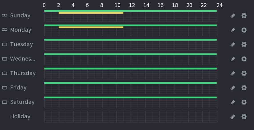
Figure 2.35
✓ Define for the whole week: Click ^9 next to All, all the icon switches to s , you can define the period for all the days simultaneously.
Define for several days of a week: Click 1=1 before each day one by one, the icon switches to define the period for the selected days simultaneously.
. You can
• On the timeline, left click mouse and then drag to define a period.
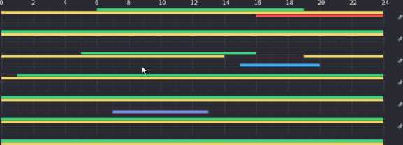
There are six periods in one day, the Device starts recoding the selected event type in the defined period. In Figure 2.36, the different color bars stand for different record types.
- Green stands for general record.
- Yellow stands for MD (motion detection) record.
- Red stands for alarm record.
- Blue stands form intelligent record.
- Orange stands for MD & Alarm record.
- Purple stands for POS record.
- Once the time period overlaps, the record priority: MD & Alarm ^ Alarm ^ POS ^ Intelligent ^ MD ^ General.
- Select a record type and then click the □ of the corresponding date to clear the corresponding period.
□ All ■ General ■ MD ■ Alarm ■ MD&Alarm ■ Intel Q POS
0 2 4 6 8 10 12 14 16 18 20 22 24
- Sunday t ©
O Monday # ©
- Tuesday ©
- Wednesday ©
O Thursday # ©
o Friday ©
- Saturday ©
Figure 2.36
The MD record and alarm record function are both null if you enabled MD & Alarm function.
![]() • Define the period by editing.
• Define the period by editing.
Select a date and then click
The Period interface is displayed. See Figure 2.37.
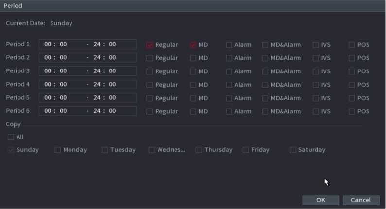
Figure 2.37
> Set record type for each period.
- There are six periods for you to set for each day.
- Under Copy, select All to apply the settings to all the days of a week, or select specific day(s) that you want
to apply the settings to.
Click Apply to save the settings.
Step 5 Click Apply to complete the settings.
Enable auto record function so that the record plan can become activated.
You can set schedule snapshot period. After set schedule snapshot, device can snapshot image according to the period you set here. For example, the alarm snapshot period is from 6:00-18:00 Monday, device can snapshot during the 6:00-18:00 when an alarm occurs.
Step 1 Click Snapshot button, device goes to following interface. See Figure 2.38.
Select Main Menu ^ STORAGE ^ SCHEDULE ^ Snapshot, you can go to the snapshot interface.

Channel
■ Alarm
»
a
o Saturday
■ MD&Aiarm ■ ivs
Q Regular ■ MD
Default
Copy
Apply
Cancel
Figure 2.38
Step 2 Select a channel to set schedule snapshot.
Step 3 Set snapshot type as schedule.
Step 4 Check the box to set alarm type. See Figure 2.39.

Figure 2.39
- When the record type is MD (motion detect), alarm, MD & Alarm, IVS and POS, enable the channel record function when corresponding alarm occurs. For example, when the alarm type is MD, select Main Menu ^ ALARM ^ VIDEO DETECTION ^ Motion Detect, select the record channel and enable record function. See Figure 2.40.
- When the record type is MD (motion detect), alarm, MD & Alarm, IVS and POS.
| Channel
Enable |
1
■~l |
Region
Sensitivity |
Setting
3 |
|
| Period | Setting | Anti-Dither | 5 | s |
| Alarm Out | Setting | Latch | 10 | s |
| |~| Show Message
Record Channel □ PTZ Activation |
[ | Alarm Upload
Setting Setting |
L 1 Send Email
Post-Record |
10 | s |
| □ Tour | Setting | F 1 Picture Storage | ||
| | | Buzzer
□ Voice Prompts |
Log
None |
|||
Apply Cancel
Figure 2.40
Step 5 Set snapshot period.
Step 6 Click Apply button to save snapshot plan.
• Enable auto snapshot function so that the snapshot plan can become activated.
After set schedule record or schedule snapshot, you need to enable auto record and snapshot function so that system can automatically record or snapshot.
- Auto: System automatically records at the type and record period you set in Schedule interface.
- Manual: System records general files for all day.

You need to have storage authorities to implement the Manual record operation. Make sure the HDD has been properly installed.
Step 1 Right click mouse and then select Manual ^ Record or select Main Menu ^ STORAGE ^ RECORD. See Figure 2.41.
![]()
For some series products, after you logged in, you can click the Rec button at the front panel to go to the Record interface.
Mainstream All 1
Auto O
Manual Q Q
off O O
Sub Streaml
Auto O O
Manual Q Q
off o
Sub Streams
Auto Q O
Manual Q Q
off O
Snapshot
Enable O O
Disable O
Apply Cancel
Figure 2.41
| Parameter | Description |
| Channel | Displays all the analog channels and the connected digital channels.
You can select a single channel or select All. |
| Record status | Auto: Automatically record according to the record type and recording time as configured in the recording schedule.
Manual: Keep general recording for 24 hours for the selected channel. Off: Do not record. |
| Snapshot status | Enable or disable the scheduled snapshot for the corresponding channels. |
Step 3 Click Apply.
Select Main menu ^ REGISTRATION ^ Camera Registration, you can register the remote device. See Figure 2.42.
Show Filter None * Uninitialized | IP Address » Search
| 12 | Edit | Preview | Status IP Address | Manufacturer | Type | MAC Address | Port | Device Name | – |
| 1 | Z | ¡LIVE | V’ 172.11.3.129 | Dahua | ATM | 20:18:01:05:… | 37777 | ATM | |
| 2 | ✓’ | LIVE | ✓ 172.11.6.47 | Dahua | HFD5PR1 | e0:50:8b:43:… | 37777 | HFD5PR1 | 1=1 |
| 3 | Z | [ÜVË | ✓ 172.11.2.141 | Dahua | IP Camera | 90:02:a9:42:… | 37777 | IP Camera | |
| 4 | z | |UVE| | >/ 172.11.111.108 | Dahua | IPC-KW100W | 90:02:a9:42:… | 56818 | IPC-KW100W | |
| 5 | ✓’ | IÜVË] | ✓ 172.11.99.88 | Dahua | IP Camera | 4c:ll:bf:9a:… | 37777 | IP Camera | |
| 6 | z | 172.11.4.33 | Dahua | EVS7072DR | 4c:ll:bf:25:… | 37777 | EVS7072DR | – | |
| < ■ | |||||||||
| Device Sea rch | Initialize Modify IP | Add | ManualAdd |
| Added Device | Link Info | ||
| Channel | Edit Delete Status IP Address Port Device Name Remote Channel CAM Name | ||
| 1 | Z ffi • 172.11.3.124 25001 NVR 1 CAM 1 |
Delete H.265 Auto Switch | Import Export
Residue bandwidth/T… 328.00Mbps/328.00…
Figure 2.42
After register the remote device to the NVR, you can view the video on the NVR, and manage and storage the video file. Different series products support different remote device amount.
Step 1 Select Main Menu ^ REGISTRATION ^ Camera Registration, check the box before the Q
camera name and then click Modify IP or click the before the camera name. Enter Modify IP
interface. See Figure 2.43.
• Check the box before several cameras, change the IP addresses of several cameras at the same time.
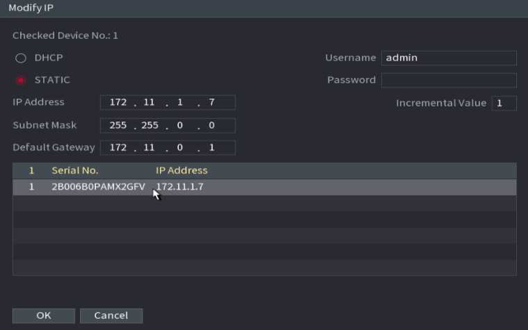
Figure 2.43
Step 2 Select IP mode.
Check DHCP, there is no need to input IP address, subnet mask, and default gateway. Device automatically allocates the IP address to the camera.
Check Static, and then input IP address, subnet mask, default gateway and incremental value.
![]()
If it is to change several devices IP addresses at the same time, input incremental value. Device can add the fourth address of the IP address one by one to automatically allocate the IP addresses.
If there is IP conflict when changing static IP address, device pops up IP conflict dialogue box. If batch change IP address, device automatically skips the conflicted IP and begin the allocation according to the incremental value
Step 3 Input remote device username and password.
![]()
When change IP addresses of several devices at the same time, make sure the cameras username and passwords are the same.
Step 4 Click OK button to save settings.
After the modification and then search again, device displays new IP address.
For the remote device that first registered to the system, it can automatically adopts encode format as H.265 if you enable H.265 Auto switch function.

![]()
Click H.265 Auto Switch button at the bottom of the interface, it is from
. The function is enabled.
See Figure 2.44.
| Show Filter None | ’ Uninitialized | IP Address ■ | Search | |||||||
| 12 Edit | Preview Status | IP Address | Manufacturer | Type | MAC Address | Port | Device Name | * | |
| 1 Z | ¡LIVE | 172.11.3.129 | Dahua | ATM | 20:18:01:05:… | 37777 | ATM | ||
| 2 Z | İLIVİ | ■y | 172.11.6.47 | Dahua | HFD5PR1 | e0:50:8b:43:… | 37777 | HFD5PR1 | = |
| 3 Z | LIVE | 172.11.2.141 | Dahua | IP Camera | 90:02 :a 9:42:… | 37777 | IP Camera | ||
| 4 Z | |uv| | 172.11.111.108 | Dahua | IPC-KW100W | 90:02 :a 9:42:… | 56818 | IPC-KW100W | ||
| 5 Z | [uve] | V- | 172.11.99.88 | Dahua | IP Camera | 4c:ll:bf:9a:… | 37777 | IP Camera | |
| 6 Z | |üv« | 172.11.4.33 | Dahua
III |
EVS7072DR | 4c:ll:bf:25:… | 37777 | EVS7072DR | ► | |
| Device Search | Initialize | Modify IP | Add | Manual Add | |||||
| Added Device | Link Info | ||||||||
| Channel | Edit | Delete Status IP Address | Port | Device Name | Remote Channel CAM Name | ||||
| 1 | Z | 1 | • 172.11.3.124 | 25001 | NVR | 1 | CAMİ | ||
| Delete | H.265 Auto Switch | B~1 | Import | Export | |||||
| Residue bandwidth/T… | 32S.00Mbps/328.00… | ||||||||
Figure 2.44
Device can export the Added device list to your local USB device.
Step 1 Insert the USB device and then click the Export button.
The Browse interface is displayed. See Figure 2.45.
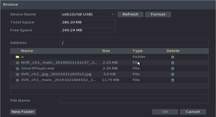
Step 2 Select Address to save export file.
Step 3 Click the OK button.
Device pops up a dialogue box to remind you successfully exported.
When exporting IP address, the File Backup Encryption check box is checked by default. The file information includes IP address, port, channel number, manufacturer, username, and password.
- If you select the File Backup Encryption check box, the file format is backup.
- If you clear the File Backup Encryption check box, the file format is .csv. In this case, there might be a risk of data
leakage.
Step 1 Click Import button.
The Browse interface is displayed. See Figure 2.46.
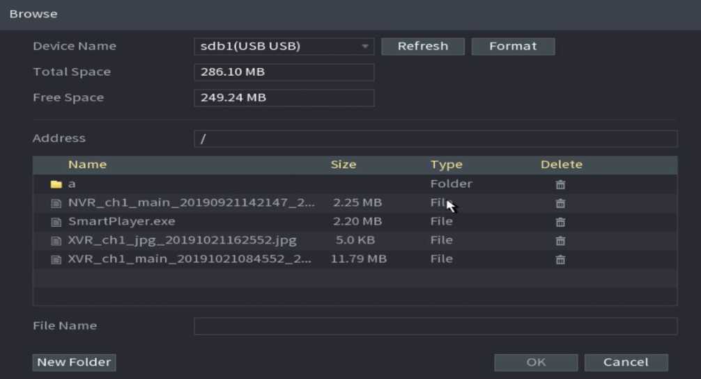
Figure 2.46
Step 2 Go to Address to select the import file and then click the OK button. System pops up a dialogue box to remind you successfully imported.
If the imported IP has conflicted with current added device, system pops up a dialogue box to remind you. You have two options.
Step 3 Click OK button.
The imported information is on the Added Device list.
Remote device initialization can change remote device login password and IP address.
When connect a camera to the NVR via PoE port, NVR automatically initialize the camera. The
camera adopts NVR current password and email information by default.
When connect a camera to the NVR via PoE port after NVR upgraded to the new version, the
NVR may fail to initialize the camera. Go to the Registration interface to initialize the camera.
Step 1 Select Main Menu ^ CAMERA -^ Camera Registration.
The Camera Registration interface is displayed.
Step 2 Click Device Search and then click Uninitialized.
Device displays camera(s) to be initialized.
Step 3 Select a camera to be initialized and then click Initialize.
The Enter Password interface is displayed. See Figure 2.47.
Enter Password
Using cu rrent device password and email mlo.
Next
Figure 2.47
Step 4 Set remote device password and email information.
![]()
If you want to use current device password and email information, the remote device automatically uses NVR admin account information (login password and email). There is no need to set password and email. Go to step 6.
Cancel Using current device password and email info, The Enter Password interface is d isplayed. SeFigure 2.48.
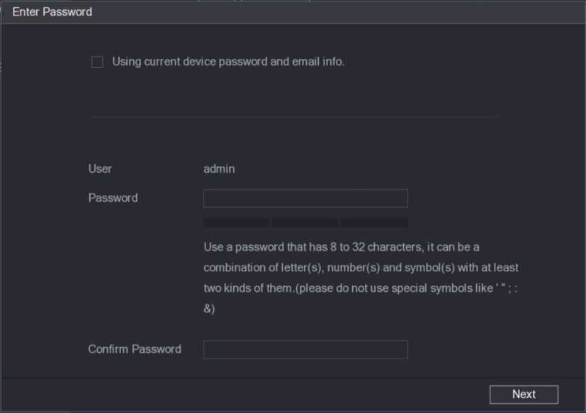
Figure 2.48
| Parameter | Description |
| User | The default is admin. |
| Password | The new password can be set from 8 characters through 32 characters and contains at least two types from number, letter and special characters (excluding , , “;”, “:” and “&”).
Enter a strong password according to the password strength bar indication. |
| Confirm Password |
For your device own safety, create a strong password of your own choosing. We also recommend you change your password periodically especially in the high security system.
Step 5 Click Next button.
The Password Protection interface is displayed. See Figure 2.49.
To reset passwad. please input properly a update in time
Back
Next Skip
Figure 2.49
Step 6 Set email information.
Input an email address for reset password purpose.
Cancel the box and then click Next or Skip if you do not want to input email information here.
Step 7 Click Next button.
The Network interface is displayed. See Figure 2.50.
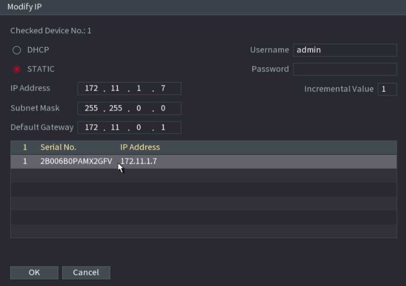
Step 8 Set camera IP address.
Check DHCP, there is no need to input IP address, subnet mask, and default gateway. Device automatically allocates the IP address to the camera.
Check Static, and then input IP address, subnet mask, default gateway and incremental value.
![]()
If it is to change several devices IP addresses at the same time, input incremental value. Device can add the fourth address of the IP address one by one to automatically allocate the IP addresses.
If there is IP conflict when changing static IP address, device pops up IP conflict dialogue box. If batch change IP address, device automatically skips the conflicted IP and begin the allocation according to the incremental value.
Step 9 Click Next button.
The Device Initialization interface is displayed. See Figure 2.51.
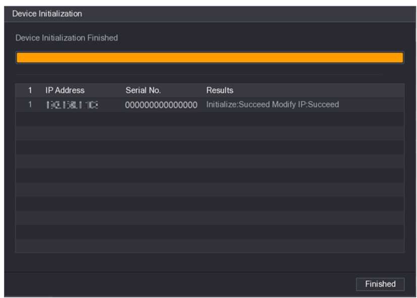
Figure 2.51
Step 10 Click Finished to complete the setup.
If you have not registered a remote device to a channel, go to the preview interface to add.
Step1 On the Preview interface, Move your mouse to window.
There is an icon “+ ” on the channel window. See Figure 2.52.
Figure 2.52
Step 2 Click “+”, device pops up interface to add network camera.
You can set network camera parameters according to different environments. It is to get the best video effect.
Step 1 Select Main Menu ^ CAMERA ■> IMAGE.
The IMAGE interface is displayed. See Figure 2.53.
Channel
Image Brightness
Contrast
Saturation
Hue
O © 0 50
O O O 50
o O 0 50
O O O 50
Exposure
BLC
WB
Day&Night
Apply Cancel
Figure 2.53

Step 2 Configure parameters.
![]()
Different series network camera displays different parameters. The actual product shall prevail.
| Parameter | Description |
| Channel | In the Channel list, select the channel that you want to configure. |
| Config File | There are three config files for you. System has configured the corresponding parameters for each file, you can select according to your actual situation. |
| Brightness | Adjusts the image brightness. The bigger the value is, the brighter the image will become. Adjusts the brightness
according to actual environment. |
| Contrast | Adjusts the image contrast. The bigger the value is, the more obvious the contrast between the light area and dark area will become. Adjusts the contrast according to actual environment. |
| Saturation | Adjusts the color shades. The bigger the value, the lighter the color will become. Adjusts the saturation according to actual environment. |
| Sharpness | Adjusts the sharpness of image edge. The bigger the value is, the more obvious the image edge is. Adjusts the sharpness according to actual environment. |
| Gamma | It is to adjust image brightness and enhance the image dynamic display range. The bigger the value is, the brighter the video is. |
| Mirror | Enable the function, the left and right side of the video image will be switched. It is disabled by default. |
| This function is for some series products only. | |
| Field of view | It is to set monitor video display direction. It includes normal, reflection, lobby 1, lobby 2. |
| Exposure | Auto iris |
according to the brightness of the environment when the iris is at the biggest value. |
|||
| 3D NR | • This function specially applies to the image which frame rate is configured as 2 at least. It reduces the noises by making use of the information between two frames. The bigger the value is, the better the effect. | ||||
| BLC | You can set camera BLC mode.
Default: The device auto exposures according to the environment’s situation so that the darkest area of the video is cleared. Customize: After select the specified zone, the system can expose the specific zone so that the zone can reach the proper brightness.
|
||||
| WB | > You can set camera WB mode. It can affect the image whole hue so that the image can accurately displays the
environment status. |
||||
| Different cameras support different WB modes such as auto, | |||||
| manual, natural light, outdoor and etc. | |||||
| Day & Night | Configure the color and black & white mode of the image. This setting is not affected by the configuration files. The default setting is Auto.
and whether there is an IR light, either color image or black & white image is output.
|
||
| The Sensor item is for some non-IR device only. | |||
Step 3 Click Apply.
You can set video bit stream and image parameters.
You can set video bit stream parameters such as bit stream type, compression, resolution.
Some series products support three streams: mainstream, sub stream 1, sub stream 2. The sub stream maximally supports 1080P.
Step1 Select Main Menu ^ CAMERA ^ ENCODE ^ ENCODE.
The ENCODE interface is d isplayed. See Figu re 2.54.
Figure 2.54
| Channel | In the Channel list, select the channel that you want to configure the settings for. |
| Smart Codec | Enable the smart codec function. This function can reduce the video bit stream for non-important recorded video to
maximize the storage space.
|
| Type | Mainstream: In the Type list, select General, MD (Motion
Detect), or Alarm. Sub Stream: This setting is not configurable. |
| Compression | In the Compression list, select the encode mode.
recommended.
definition.
higher bit stream compared with other settings for the same definition |
| Resolution | In the Resolution list, select resolution for the video. The maximum video resolution might be different dependent on your device model. |
| Frame Rate
(FPS) |
Configure the frames per second for the video. The higher the value is, the clearer and smoother the image will become. Frame rate changes along with the resolution.
Generally, in PAL format, you can select the value from 1 through 25; in NTSC format, you can select the value from 1 through 30. However, the actual range of frame rate that you can select depends on the capability of the Device. |
| Bit Rate Type | In the Bit Rate Type list, select CBR (Constant Bit Rate) or VBR (Variable Bit Rate). If you select CBR, the image quality cannot be configured; if you select VBR, the image quality can be configured. |
| Quality | This function is available if you select VBR in the Bit Rate List. The bigger the value is, the better the image will become. |
| I Frame Interval | The interval between two reference frames. |
| Bit Rate (Kb/S) | In the Bit Rate list, select a value or enter a customized value to change the image quality. The bigger the value is, the better the image will become. |
Step 2 Configure parameters.
Step 3 Click More Setting.
The More Setting interface is displayed. See Figure 2.55.
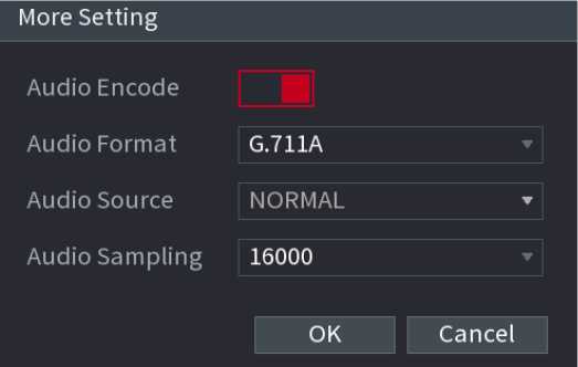
Figure 2.55
| Parameter | Description |
| Audio Encode | This function is enabled by default for mainstream. You need to manually enable it for sub stream 1. Once this function is enabled, the recorded video file is composite audio and video stream. |
| Audio Format | In the Audio Format list, select a format: G711a, G711u, PCM, AAC. |
| Audio Sampling | In the Audio Sampling list, you can select audio sampling rate. |
Step 5 Click OK.
Back to Encode interface.
Step 6 Click Apply.
You ca n set snapshot mod e, i mage size, q ua l ity a nd i nte rva l .
Stepl Select Main Menu ^ CAMERA ^ ENCODE ^ Snapshot.
The SNAPSHOT interface is displayed. See Figure 2.56.
Default
Refresh
Apply Cancel
| Snapshot | 1 | /Time |
| Channel | 2 | – |
| Mode | Timing | |
| Image Size | 1280×720(720P) | |
| Image Quality | 5 | |
| Interval | 1 Second |
Figure 2.56
| Parameter | Description |
| Manual Snap | In the Manual Snap list, select how many snapshots you want to take each time. |
| Channel | In the Channel list, select the channel that you want to configure the settings for. |
| Mode | In the Mode list, you can select Timing, or Trigger. |
| Timing: The snapshot is taken during the scheduled period. Trigger: The snapshot is taken when there is an alarm event occurs, such as motion detection event, video loss, and local alarms. | |
| Image Size | In the Image Size list, select a value for the image. The bigger the value is the better the image will become. |
| Image Quality | Configure the image quality by 6 levels. The higher the level is, the better the image will become. |
| Interval | Configure or customize the snapshot frequency. Max.
supports 3600 seconds/image. |
Step 3 Click Apply.
You can set customized channel name.
Stepl Select Main Menu ^ CAMERA ^ CAM NAME.
The CAM NAME interface is displayed. See Figure 2.57.
| Dl CAM 1 D2 | CAM 2 |
| D3 HAHA1HH D4 | IPC |
| D5 CAM 5 D6 | CAM 6 |
| D7 CAM 7 D8 | CAM 8 |
| D9 CAM 9 DIO | CAM 10 |
| Dll CAM 11 D12 | CAM 12 |
| D13 CAM 13 D14 | CAM 14 |
| D15 CAM 15 D16 | CAM 16 |
1/4 >
Default Refresh
Apply Cancel
Figure 2.57
You can only change the camera connected via the private protocol. The channel name supports 63 English characters.
Step 3 Click Apply.
You can upgrade the connected network camera firmware. It includes online upgrade and file upgrade.
Step 1 Select Main Menu ^ CAMERA ^ REGISTRATION ^ Upgrade.
The Upgrade interface is displayed. See Figure 2.58.
S’OWW

iUftüpfiad«
Figure 2.58
Step 2 Update the firmware of the connected remote device.
- Select a remote device and then click the Detect button on the right side or check a box to select a remote device and then click Manual Check.
- System detects the new version on the cloud.
- Select a remote device that has new version and then click online upgrade.
- After successful operation, system pops up upgrade successful dialogue box.
- Select a channel and then click File Upgrade. Select upgrade file on the pop-up interface.
- Select the upgrade file and then click OK button.
After successful operation, system pops up upgrade successful dialogue box.
![]()
If there are too much remote devices, select Device Type from the drop-down list to search the remote device you desire.
You can view the connection and alarm status of the corresponding channel.
Select Main Menu ^ CAMERA ^ REGISTRATION ^ Status, the Status interface is displayed. See Figure 2.59.
CtunnH SUtut tfAddmi HD video Ims ÎJ»î»pertn< AlatMln Cmmu Km** MAmita twer îjp*
1< • ItUAM CF Flui
14 • l’Za.I JO — — — – CP Plus
| Icon | Description | Icon | Description |
| □ | IPC works properly. | IPC does not support. | |
| There is an alarm. | □ | Video loss occurs. |
You ca n view IP add ress, manufacturer, type, system ve rsion of the co n nected re mote device.
Select Main Menu ^ CAMERA ^ REGISTRATION ^ Firmware, the Firmware interface is displayed. See Figure 2.60.
L*nuf*cturer T»pe System vemon Ma Vhtoo
CP PLUS CP-UNC-H.. 2.4SOj0O01. CP2LO1SO– 1 CP PLUS
After you logged in, the system goes to multiple-channel live view mode by default. You can view the monitor video of each channel. The displayed window amount may vary. The actual product shall prevail.
On Preview interface, you can view the monitor video of each channel. The corresponding channel displays date, time, and channel name after you overlay the corresponding information. Refer to the following table for detailed information.
| SN | Icon | Description |
| 1 | MoB | When current channel is recording, system displays this icon. |
| 2 | n | When motion detection alarm occurs, system displays this icon. |
| 3 | 1 | When video loss alarm occurs, system displays this icon. |
| 4 | fi | When current channel is in monitor lock status, system displays this icon. |
| 5 | When the device connects to the network camera remotely, system displays this icon.
This function is for some series products only. |
You can quickly perform operation through the icon on the navigation bar.
![]()
Different series products may display different navigation bar icons. Refer to the actual product for detailed information.
Select Main Menu ^ SYSTEM ^ GENERAL ^ General to enable navigation bar function and then click Apply; otherwise you cannot see the following interface.
Step1 On the preview interface, left click mouse, You can see navigation bar. See Figure 2.61.

Figure 2.61
| Icon | Function | ||
| o | Open Main Menu. | ||
| 0 | Expand or condense the navigation bar. | ||
| LULUS | Select view layout. | ||
| Go to the previous screen. | |||
| IË1 | Go to the next screen. | ||
| ■ | Enable tour function. The icon switches to. | ||
| Close the tour or the triggered tour operation has cancel | |||
| led, device restores the previous preview video. | |||
| □ | Open the PTZ control panel. For details, see “ PTZ Control”.” | ||
| Open the Color Setting interface. For details, see “ PTZ Control.“ | |||
| This function is supported only in single-channel layout. | |||
| □ | Open the record search interface. For detail, see “4.6.2 Search Interface.“ |
| Open the Broadcast interface. For detail, see “4.17.3 Broadcast.“ | |
| H | Open the EVENT interface to view the device alarm status. For details, see “4.8.2 Alarm Status.“ |
| ■ | Open the CHANNEL INFO interface to display the information of each channel. For details, see “ 4.3.2.1 Channel Info.“ |
| Open the CAMERA REGISTRATION interface. For details, see “4.1.4.4 Registration.“ | |
| Open the NETWORK interface. For details, see “ 4.12 Network.“ | |
| Fl | Open the HDD MANAGER interface. For details, see “ 4.13.3 HDD.“ |
| □ | Open the USB MANAGER interface. For details about USB operations, see “ 4.3.2.2 USB Manager.“ |
After the remote device registered to the corresponding channel, you can view its status such as alarm status, record status, connection status, record mode, etc.
- Alarm status: It includes motion detection alarm, video loss alarm, tampering alarm.
- Record status: System is recording or not.
- Bit Rate: System displays bit rate information.
- Status: current channel connection status.
![]()
Click button
, system goes to the channel information setup interface. You can view information of the corresponding
channel. See Figure 2.62.

Figure 2.62
After connecting the USB device, you can copy log, config file to USB device or update NVR system.
Click , system goes to HDD Manager interface. You can view and manage HDD information. See Figure 2.63. Here you can view USB information, backup file, and update system.
USB MANAGER
Type Total Space Used Space Free Space
Name
Config Backup
System Upgrade
Figure 2.63
2.5.5.
Move your mouse to the top center of the video of current channel; you can see system pops up the preview control interface. See Figure 2.64. If your mouse stays in this area for more than 6 seconds and has no operation, the control bar automatically hides.
Slight difference may be found on the user interface.
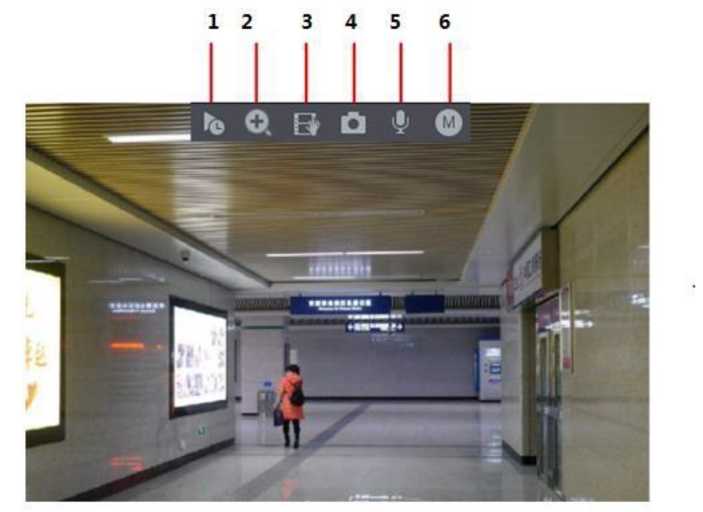
Figure 2.64
![]()
You can playback the previous 5-60 minutes record of current channel. Click
to go to the instant replay interface. See

Figure 2.65
Instant replay is to playback the previous 5 minutes to 60 minutes record of current channel. Move the slider to choose the time you want to start playing. Play, pause and close playback.
The information such as channel name and recording status icon are shielded during instant playback and will not display until exited. During playback, screen split layout switch is not allowed.
Tour high higher priority than the instant playback. The instant playback function is null when tour function is in process and the preview control interface auto hides either. The function becomes valid again after tour is complete.
Go to the Main Menu ^ SYSTEM ^ GENERAL ^ General to set Instant Replay time. See Figure 2.66.
System may pop up a dialogue box if there is no such record in current channel.
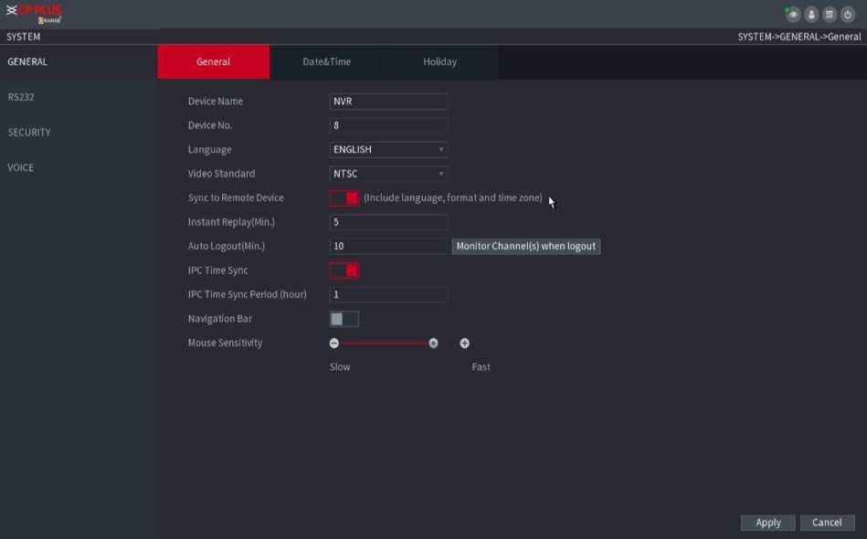
Figure 2.66
You can zoom in specified zone of current channel so that you can view the details. It supports zoom in function of multiple channel. It includes the following two ways:
Click □, the icon switches to ^3. Hold down the left mouse button to select the area you want to enlarge. The area is enlarged after the left mouse button is released. Point to the center that you want to enlarge, rotate the wheel button to enlarge the area.
![]()
For some models, when the image is enlarged in the first way described previously, the selected area is zoomed proportionally according to the window.
The digital zoom interface is shown as in Figure 2.67. When the image is in the enlarged status, you can drag the image toward any direction to view the other enlarged areas. Right click mouse to cancel zoom and go back to the original interface.

Figure 2.67
![]()
You can record the video of any channel and save the clip into a USB storage device. By clicking
, the recording is
started. To stop recording, click this icon again. The clip is automatically saved into the connected USB storage device.
You can record the video of any channel and save the clip into a USB storage device.
You can take one to five snapshots of the video and save into a USB storage device. By clicking —, you can take snapshots. The snapshots are automatically saved into the connected USB storage device. You can view the snapshots on your PC.
![]()
To change the quantity of snapshots, select Main Menu ^ CAMERA ^ ENCODE ^ Snapshot, in the Manual Snap list, select the snapshot quantity.
You can perform the voice interaction between the Device and the remote device to improve efficiency of emergency.
![]()
![]()
Step1 Click button
to start bidirectional talk function the icon now is shown as
. Now the rest bidirectional talk
buttons of digital channel become null too.
![]()
Step2 Click
again, you can cancel bidirectional talk. Switch bit streams Via this function, you can switch the channel
mainstream/sub stream according to current network bandwidth.
M: Mainstream. Its bit streams are big, and definition is high. It occupies large network bandwidth suitable for video wall surveillance, storage etc.
S: Sub stream. Its definition is low but occupies small network bandwidth. It is suitable for general surveillance, remote connection etc.
![]()
Click
to switch the bit stream type of the mainstream and sub stream.
M: Mainstream.
S: Sub stream. Some series products support two sub streams (S1, S2).
Right-Click Menu: By right-clicking the menu, you can quickly access the corresponding functional interface and perform relevant operations, including entering the main menu, searching records and selecting screen split mode. Right-click on the preview interface and the right-click menu is displayed. See Figure 2.68.
The right-click menu is different for different models. The actual interface shall prevail.
Main Menu
Q. Search
Z PTZ
■ View 1 ►
i! View 4 ►
■i View 8 ►
::: View 9 ►
iiii View 16 ►
EE View 25 ►
EE View 36 ►
U Sequence
© Smart Tracking
Ei Custom Split ►
W Camera Registration
• Manual ►
C Preview Mode ►
B Crowd Distribution ►
EC Auto Focus
S Image E Sub Port
Figure 2.68
| Function | Description |
| Main Menu | Open Main Menu interface. |
| Search | Open the PLAYBACK interface where you can search and play back record files. For details, see “4.6 Playback and Search.“ |
| PTZ | Open the PTZ interface. For details, see “4.4 PTZ.“ |
| View
1/4/8/9/16/25/36 |
Configure the live view screen as a single-channel layout or multi-channel layout. |
| Sequence (View Layout) | Set customized screen split mode and channels. For details, see “4.3.4 Sequence.“ |
| Previous Screen
Next Screen |
Click Previous Screen to go to the previous screen. For example, if you are using 4-split mode, the first screen is displaying the channel 1-4, click Next screen, you can view channel 5-8. |
| Camera Registration | Open the CAMERA REGISTRATION interface. |
| Manual | Select Record, you can configure the recording mode as Auto or Manual or stop the recording. You can also enable or disable snapshot function Select Alarm Out; you can configure alarm output settings. |
| Preview Mode | There are two modes: regular/AI mode. |
| Crowd Distribution | Select enable/disable to start/stop crowd distribution |
| Auto focus | Click to realize auto focus function. Make sure the connected camera supports auto focus function. |
| Image | Click to modify the camera properties. |
| Sub Port | Click Sub Port, you can go to control the sub screen. |
You can set customized view layout.

The preview layout restores default channel layout after Default operation.
Step1 On the preview interface, right click mouse and then click Sequence. The Sequence interface is displayed. See Figure 2.69.
- Enter edit view interface, device automatically switches to the max split amount mode.
- The channel list on the edit view interface displays the added camera channel number and channel name.
leans camera is online.
Means camera is offline.
- In case the channel amount has exceeded the device max split amount, the edit view interface can display the max screen number amount and current screen number.
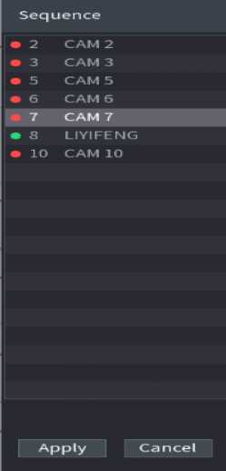
Figure 2.69
Step 2 On the edit view interface, drag the channel to the desired window, or drag on the preview window to switch the position.
Check the channel number at the right bottom corner to view the current channel sequence. See Figure 2.70.
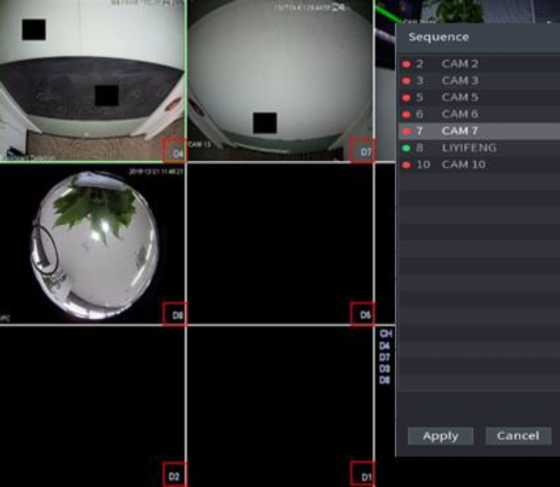
Figure 2.70
Step3 Click Apply to save current channel sequence. After you change the channel sequence, click Cancel button or right click mouse, device pops up the dialogue box. See Figure 2.71.
- Click OK to save current settings.
- Click No to exit without saving the settings.
The channel sequence has changed,doyou want to save it now?
Figure 2.71
PTZ is a mechanical platform that carries a camera and a protective cover and performs overall control remotely. A PTZ can move in both horizontal and vertical direction to provide all-around view to the camera.
Before you control the PTZ, make sure the PTZ decoder and the NVR network connection is OK.
You can set different PTZ parameters for local type and remote type. Before you use local PTZ, make sure you have set PTZ protocol; otherwise you cannot control the local PTZ.
Local: The PTZ device connects to the NVR via the cable.
Remote: The PTZ device connects to the NVR via the network.
This function is for some series products only.
Step1 Select Main Menu ^ CAMERA ^ PTZ.
Step2 The PTZ interface is displayed. See Figure 2.72 (Local).
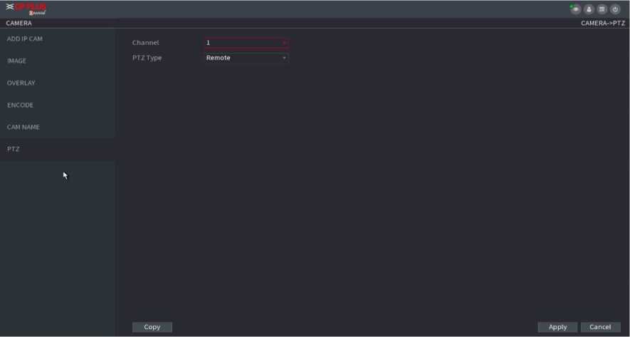
Figure 2.72
| Parameter | Description |
| Channel | In the Channel list, select the channel that you want to connect the PTZ camera to. |
| PTZType |
camera to the Device. |
| Protocol | In the Protocol list, select the protocol for the PTZ camera such as PELCOD. |
| In the Address box, enter the address for PTZ camera. The default is 1. | |
| Address | The entered address must be the same with the address configured on the PTZ camera; otherwise the system cannot control PTZ |
| camera. | |
| Baud rate | In the Baud rate list, select the baud rate for the PTZ camera. The default is 9600. |
| Data Bits | The default is 8. |
| Stop Bits | The default is 1. |
| Parity | The default is NONE. |
PTZ control panel performs the operations such as directing camera in eight directions, adjusting zoom, focus and iris settings, and quick positioning.
Right-click on the live view screen and then select PTZ. The PTZ control panel is displayed. See Figure 2.73.
X Speed 5
- Zoom +
- Focus +
- Iris +
Figure 2.73
![]()
The gray button means system does not support current function. For some series products, the PTZ function is valid in one- window mode.
| Parameter | Description | |
| Speed | Controls the movement the movement will be. | speed. The bigger the value is, the faster |
| Zoom | 9: Zoom out. ^3: Zoom in. | |
| Focus | 9: Focus far. ^3: Focus near. | |
| Iris | 9: Image darker. ^3: Image brighter. | |
Supports eight directions.
PTZ movement
| H | Fast positioning button.
Positioning: Click to enter the fast positioning screen, and then cl ick a nywhere on the l ive view screen, the PTZ wi l l tu rn to this point and move it to the middle of the screen. Zooming: On the fast positioning screen, drag to draw a square on the view. The sq ua re supports zoom i ng. Dragging upward is to zoom out, and dragging downward is to zoom in. The smaller the square, the larger the zoom effect. This function is for some series products only and can only be controlled through mouse operations. |
||
| □ | Click □, you can control the four directions (left, right, up, and down) PTZ movement through mouse operation. | ||
| ■ | Click ^^1 to open the expanded PTZ control panel. | ||
![]()

![]()
On the basic PTZ control panel, click
to open the expanded PTZ control panel to find more options. See Figure 2.74.
Figure 2.74
The functions with buttons in gray are not supported by the system.
Right-click once to return to the interface of PTZ basic control panel.
| Icon | Function | Icon | Function | ||
| Preset | Auto Pan | ||||
| A | Tour | H | Flip | ||||
| IS | Pattern | Reset | |||||
| Auto scan | Click the AUX Config icon to open the PTZ functions settings
interface. |
||||||
| ? | AUX Switch | □ | Click the Enter Menu icon to open the MENU OPERATION interface. | ||||
Step 1 On the Expanded PTZ Control Panel, click |Ol The Preset interface is displayed. See Figure 2.75.
PTZ
Preset Tour Pattern Border
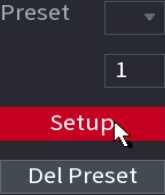
Figure 2.75
Step4 Click the direction arrows to the required position.
Step5 In the Preset box, enter the value to represent the required position.
Step6 Click Setting to complete the preset settings.
Step1 On the Expanded PTZ Control Panel, click IO The PTZ interface is displayed.
Step2 Click the Tour tab.
The Tour tab is displayed. See Figure 2.76.
| Preset | Toajt | Pattern | Border |
| Preset | 1 | ||
| Patrol… | 1 | ||
| < | ► |
Add Preset
Del Preset
Del Tour
Figure 2.76
Step3 In the Patrol No. box, enter the value for the tour route.
Step4 In the Preset box, enter the preset value.
Step5Click Add Preset.
A preset will be added for this tour.
![]()
You can repeat adding more presets. Click Del Preset to delete the preset for this tour. This operation can be repeated to delete more presets. Some protocols do not support deleting.
Step1 On the Expanded PTZ Control Panel, click The PTZ interface is displayed.
Step2 Click the Pattern tab.
The Pattern interface is displayed. See Figure 2.77.
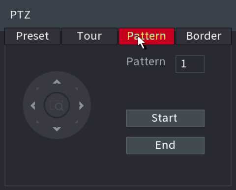
Figure 2.77
Step3 In the Pattern box, enter the value for pattern.
Step4 Click Start to perform the directions operations. You can also go to the PTZ Control Panel to perform the operations of adjusting zoom, focus, iris, and directions.
Step5 On the PTZ interface, click End to complete the settings.
Stepl On the Expanded PTZ Control Panel, click .
The PTZ interface is displayed.
Step2 Click the Border tab.
The Border interface is displayed. See Figure 2.78.
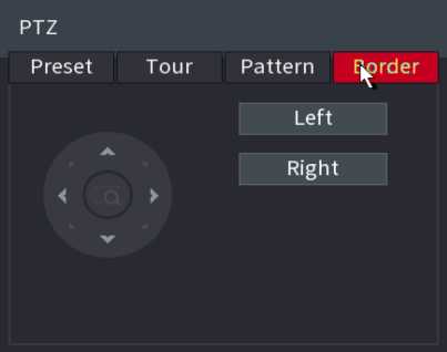
Figure 2.78
Step3 Click the direction arrows to position the left and right borders.
After you have configured the PTZ settings, you can call the PTZ functions for monitoring from the Expanded PTZ Control Panel. See Figure 2.79.

Figure 2.79
Stepl On the Expanded PTZ Control Panel, in the No. box, enter the value of the preset that you want to call.
Step2 Click to call the preset.
Step3 Click 1^31 again to stop calling the preset.
Stepl On the Expanded PTZ Control Panel, in the No. box, enter the value of the tour that you want to call.
Step2
to call the tour.
Step3
again to stop calling the tour.
Stepl On the Expanded PTZ Control Panel, in the No. box, enter the value of the pattern that you want to call.
Step2
to call the pattern.
The PTZ camera moves according to the configured pattern repeatedly.
again to stop calling the pattern.
Step3
Step 1 On the Expanded PTZ Control Panel, in the No. box, enter the value of the border that you want to call.
Step2 Click .
The PTZ camera performs scanning according to the configured borders.
again to stop auto scanning.
Step3
Stepl On the Expanded PTZ Control Panel, click S
to start moving in horizontal direction.
Step2 Click IS
again to stop moving.
, the AUX setting interface is displayed. See Figure 2.80. In the Direct
On the Expanded PTZ Control Panel, click
Aux list, select the option that corresponds to the applied protocol. In the Aux Num box, enter the number that corresponds to the AUX switch on the decoder.
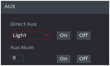
Device adopts 24-hour continuous record by default. It supports customized record period and record type.
You can view the record file of previous 5 to 60 minutes.
You can search and playback the record fine on the NVR. Select Main Menu > PLAYBACK, or on the preview interface right click mouse and then select Search, you can go to the following interface. See Figure 2.81.
The following figure for reference on
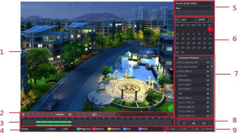
| 1 | Display Window | Display the searched recorded video or picture. It supports playing in single-cha nnel, 4-channel, 9-channel, and 16- chan nel simultaneously. | ||
| When playing back in a single channel mode, hold down the left mouse button to select the area that you want to enlarge. The area is enlarged after the left mouse button is released. | ||||
| To exit the enlarged status, right-click on the image. | ||||
| 2 | Playback
Controls Bar |
Playback control buttons. | ||
| Clip | Click to edit the record file and then save specified
footages. |
|||
| Backup | Click ^^3 to backup record. | |||
| 3 | Time Bar | Display the type and time period of the current recorded video.
displayed; in the other view layouts, only one time bar is displayed.
certain time.
settings, rotate the wheel button on the time bar, the time bar is zooming in from 0. In the situation when playback is ongoing, rotate the wheel button on the time bar, the time bar is zooming from the time point where the playback is located.
indicates external alarm; Yellow indicates motion detection; Blue indicates intelligent events; Purple indicates POS events.
area in the time bar, the system automatically jumps to the next time point where there is a recorded video located. |
||
| 4 | Play Status | Includes two playback status: Play and Stop. | ||
No.
Function
Description
| Sync | Select the Sync check box to simultaneously play recorded videos of different channels in the same period in multichannel view. | |
| Record type | Select the check box to define the recording type to search for. | |
| 5 | Search type | Select the content to play back: Record, PIC, Splice
Playback. |
| 6 | Calendar | Click the date that you want to search, the time bar displays the corresponding record.
The dates with record or snapshot have a small solid circle under the date. |
want to play back.
channel(s). |
||
| View Layout and Channel Selection | For example, if you select one channel, the playback is displayed in the single-channel view; if you select two to four channels, the playback is displayed in the four- channel view. The maximum is eight channels. | |
| Click to switch the streams Issl indicates mainstream | ||
| and IfiSI indicates sub stream. | ||
| This area includes Mark List and File List. | ||
| Different series products have different functions. The icons displayed may vary. The actual product shall prevail. | ||
| List Display | • ^3: Click the Mark List button, the marked recorded | |
| 8 | video list is displayed. Double-click the file to start playing. | |
video list is displayed. You can lock/unlock the files.
fisheye video. |
||
| 9 | Time Bar Unit | You can select 24hr, 2hr, 1hr, or 30min as the unit of time bar. The time bar display changes with the setting. |
All the operations here (such as playback speed, channel, time and progress) have relationship with hardware version. Some series NVRs do not support some functions or playback speeds.
The playback control interface is shown as below. See Figure 2.82.

Figure 2.82
Refer to the following sheet for more information.
| Icon | Function | ||
| □ m | Play/Pause
In slow play mode, click it to switch between play/pause. |
||
| □ | Stop
When playing back, click to stop current playback process. |
||
| □ | Backward play
In normal play mode, left click the button, the file begins backward play. Click it again to pause current play. In backward play mode, click ^3or to restore normal play. |
||
| □ □ | Display previous frame/next frame.
When pause the normal playback file, click ^31 or LU to playback frame by frame. In frame by frame playback mode, click ^3 or EH to resume normal playback mode. |
||
| Slow play
In playback mode, click it to realize various slow play modes such as slow play 1, slow play 2, and etc. |
|||
| □ | Fast forward
In playback mode, click to realize various fast play modes such as fast play 1, fast play 2 etc. |
||
| Icl | Adjust the volume of the playback. | ||
| Smart search | |||
| □ | Click the snapshot button in the full-screen mode, the system can snapshot 1 picture.
System supports custom snap picture saved path. Connect the peripheral device first, click snap button on the full-screen mode, you can select or create path. Click Start button, the snapshot picture can be saved to the specified path. |
||
| □ | Mark button
This function is for some series product only. Make sure there is a mark button in the playback control pane. |
||
| ||^j | Display/hide POS information
In 1-channel playback mode, you can click it to display/hide POS information on the video. |
||
| ■ | In 1-channel playback mode, click it to enable/disable display IVS rule information on the video. | ||
| This function is for some series only. | |||
You can search the recorded videos, splice, or snapshots from HDD or external storage device. From R/W HDD: Recorded videos or snapshots playback from HDD of the Device. See Figure 2.83.

Figure 2.83
From I/O Device: Recorded videos playback from external storage device. See Figure 2.84. Click Browse, select the save path of recorded video file that you want to play. Double-click the video file or click ^3 to start playing.
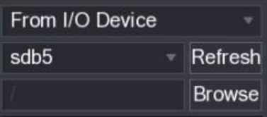
Figure 2.84
This function allows you to clip some footages to a new file and then save it to the USB device. See Figure 2.85. Follow the steps listed below.
Step1 Select a record first and then click ^3 to playback.
Step2 Select a time at the time bar and then click B to start clip.
Step3 Select a time at the time bar and then click B
to stop clip.
IS1
Step4 Click , system pops up dialogue box to save the clip file.
![]()

Figure 2.85
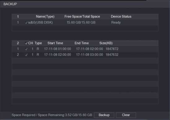
Figure 2.86
Clip function is for one-channel/multiple-channel.
Max save 1024 files at the same time.
This function is not for the file already checked in the file list.
This function is to backup files you checked in the file list, or the file you just clip.
Step1 Select the recorded video file that you want to back up.
You can select the following two types of files:
Recorded video file: Click ^3, the File List area is displayed. Select the file(s) that you want to back up. Saves the clip footages as a record file.
Step2 Click , the BACKUP interface is displayed. See Figure 2.86.
Step3 Click Backup to begin the process.
This function is for some series product only.
During playback process, it can analyze the motion detect zone in the scene and give the analysis result. This function is for channel that already enabled motion detect function (Main Menu ^ ALARM ^ VIDEO DETECT ^ Motion Detect).
Step1 Select a channel to playback video and then click
. You can view the grids on the playback video.
This function is for one-channel playback mode.
If you are in multiple-channel playback mode, double-click a channel first to switch to one-channel playback mode.
Step2 Left click mouse and then drag to select smart search zones (22*18 (PAL) , 22*15 (NTSC) ).
Step3 Click to go to smart search and playback. System is going to playback all motion detects record footages.
again to stop smart search function.
Step4 Click
The motion detect region cannot be the full screen zone.
The motion detect region adopts the current whole play pane by default.
Selects the other file on the list, system begins playing the motion detect footages of another file.
The time bar unit switch, backward play, frame by frame are null when system is playing motion detect file.
When you are playback record, you can mark the record when there is important information. After playback, you can use time, or the mark key words to search corresponding record and then play. It is very easy for you to get the important video information.
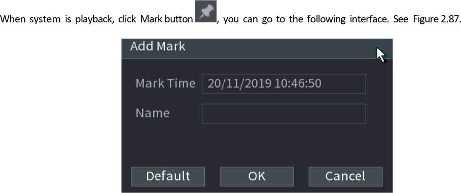
Figure 2.87
- Playback Mark
![]()
During 1-window playback mode, click mark file list button
in Figure 2.88, you can go to mark file list interface.
Double-click one-mark file, you can begin playback from the mark time.
- Play before mark time
Here you can set to begin playback from previous N seconds of the mark time.
Usually, system can playbacks previous N seconds record if there is such kind of record file. Otherwise, system playbacks from the previous X seconds when there is such as kind of record.
- Mark Manager
![]()
Click the mark manager button
on the Search interface (Figure 2.88); you can go to Manager interface. See
Figure 2.88. System can manage all the record mark information of current channel by default. You can view all mark information of current channel by time.
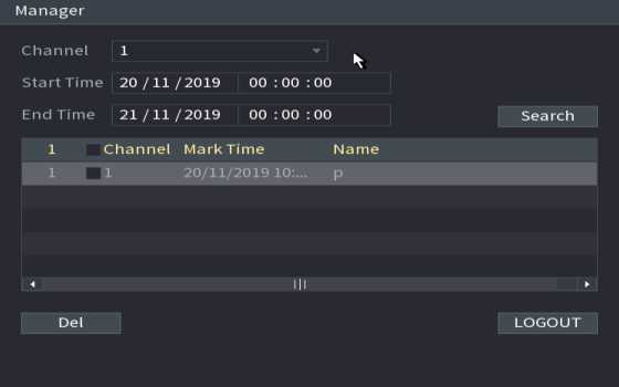
Figure 2.88
- Modify
Double-click one-mark information item, you can see system pops up a dialogue box for you to change mark information. You can only change mark name here.
- Delete
Here you can check the mark information item you want to delete and then click Delete button; you can remove one- mark item.
![]()
After you go to the mark management interface, system needs to pause current playback. System resume playback after you exit mark management interface.
If the mark file you want to playback has been removed, system begins playback from the first file in the list.
Here you can search and play the image. Follow the steps listed below.
Step1 Select Main Menu ^ PLAYBACK, or on the preview window right click mouse and then click Search, you can go to the Search interface.
Step2 At the top right corner, select image and then input playback interval.
![]()
Step 3 Select date and channel, click
to play.
You can clip the recorded video files into splices and then play back at the same time to save your time.
This function is for some series products only.
Stepl Select Main Menu > PLAYBACK, the PLAYBACK interface is displayed.
Step2 In the Search Type list, select Splice Playback; In the Split Mode list, select 4, 9, or 16. See Figure 2.89.
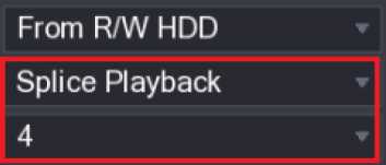
Figure 2.89
Step3 In the Calendar area, select a date.
Step4 In the CAM NAME list, select a channel.
![]()
Only single channel supports this function.
Step5 Start playing back splices. See Figure 2.90.
• Click , the playback starts from the beginning.
![]()
Double-click anywhere on the time bar, the playback starts from where you click.
Figure 2.90
E3
Click
, system displays file list. It displays the first channel of the record. See Figure 2.91
StartTime Type 0000 00 R 01:00:00 R 02:00 00 R 03:00:00 R 04:00:00 R 05:00:00 R 06:00:00 R 07:00:00 R 08-00:00 R 09:00 00 R 10:00 00 R 11:00:00 R
![]()
Start Time 17-11-08 00:00:00
End Time
17-11-08 01:00:00
Size(KB) 1847776
Figure 2.91
Check a file name, double-click the file or click ^3 to play.
Input accurate time at the top column, you can search records of current day.
System max displays 128 record files in one list.
Click Q to go back to the calendar/channel selection interface.
![]() To lock the recorded video, on the File List interface, select the check box of the recorded video, and then click
To lock the recorded video, on the File List interface, select the check box of the recorded video, and then click
the FILE LOCKED interface is
The locked video will not be overwritten. To view the locked information, click displayed.
The recorded video that is under writing or overwriting cannot be locked.
To unlock the recorded video, in the FILE LOCKED interface, select the video, and then click Unlock. See Figure 2.92.
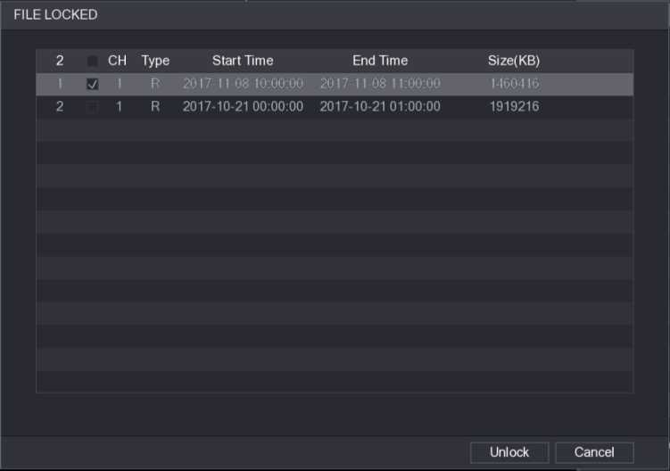
Figure 2.92
I n 1-wi n d ow playback mode, left cl ick m ou se to select a ny zo ne on th e scree n, you ca n zoom in current zone. Right click mouse to exit.
During playback mode, select from the dropdown list to switch playback channel. The smart search channel does not support this function either. When system is playing back the record file, click the number button at the front panel, system begins playing the record file of selected channel dated the same time.
You can search the record file on the NVR and filter the record file meets the corresponding rule. It is suitable for you to play the specified file.
![]()
This series NVR products support playback the AI by camera file only. AI by camera means the connected camera does all the AI analytics, and then gives the results to the NVR.
You can search the detected faces and play back.
Step1 Select Main Menu ^ AI ^ SMART SEARCH ^ FACE DETECTION. The FACE DETECTION interface is displayed. See Figure 2.93
Channel
Start Time
15/11/2019 00:00:00
End Time
15/11/2019
23:59:59
Gender
AIL
 Age
Age
AIL
All
Beard
Mask
Exp.
Glasses
Figure 2.93
Step2 Select the channel, enter the start time and end time, and set for the gender, age, glasses, beard, and mask. Click
Step 3 Select the face that you want to play back.
The picture with registered information is displayed. You can also do the following operations to the recorded files. To back up the recorded files to the external storage device, select files, click Backup, select the save path and file type, and then click Start. See Figure 2.94
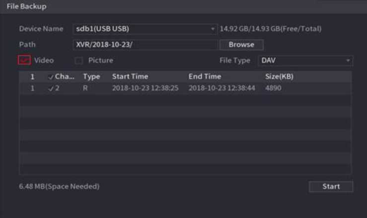
Figure 2.94
To lock the files to make it unable to be overwritten, select the files, and then click Lock. To add a mark to the file, select the files and then click Add Mark. Go to Face Properties and Person Details to view detailed information.
System can search and compare the human face on the video with the face image on the database, and playback the corresponding record file. The AI search includes two ways: Search by attributes and search by image.
This function is for some series products only.
Step1 Select Main Menu ^ AI ^ SMART SEARCH ^ FACE RECOGNITION ^ Search by Attributes. The Search by Attributes interface is displayed. See Figure 2.95.

Step2 Select the channel and set the parameters such as start time, end time, gender, age, glasses, beard, mask, and similarity according to your requirement.
Step3 Click Smart Search.
The search result is displayed. See Figure 2.96.
The human face in the image is pixelated. The actual image is clear.
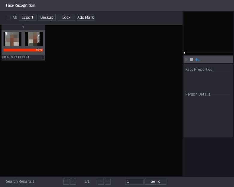
Figure 2.96
Step4 Click the picture that you want to play back.
The picture with registered information is displayed. You can also do the following operations to the recorded files. To back up the recorded files to the external storage device, select files, click Backup, select the save path and file type, and then click Start. See To lock the files to make it unable to be overwritten, select the files, and then click Lock.
To add a mark to the file, select the files and then click Add Mark. Go to the Face Properties and Person Details to view detailed information.
You can search and playback the alarm record files.
Step1 Select Main Menu ^ AI ^ SMART SEARCH ^ IVS.
The IVS interface is displayed. See Figure 2.97.
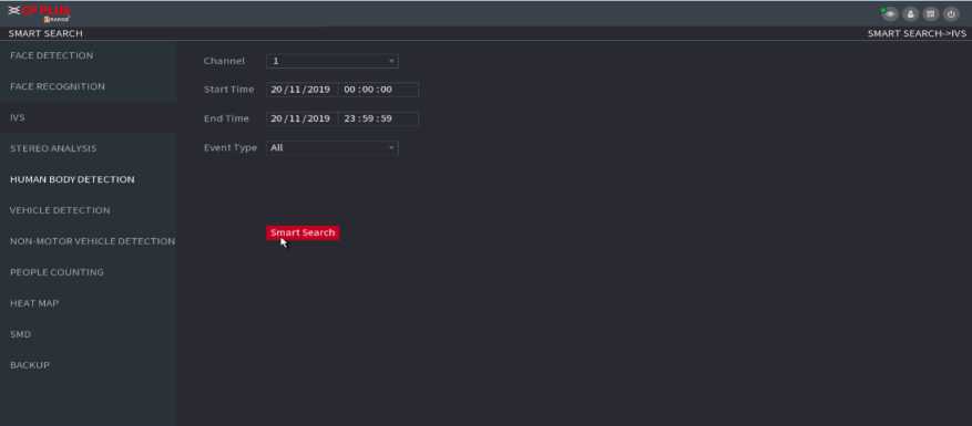
Figure 2.97
Step2 Select a channel, start time, end time, event type, and then click Smart search, the search result is displayed.
Step 3 Click the picture that you want to play back.
You can also do the following operations to the recorded files. To back up the recorded files to the external storage device, select files, click Backup, select the save path and file type, and then click Start. To lock the files to make it unable to be overwritten, select the files, and then click Lock. To add a mark to the file, select the files and then click Add Mark. Go to the Face Properties and Person Details to view detailed information.
You ca n sea rch th e human body a nd sea rch the alarm record d u ri ng th e specified period .
Step1 Select Main Menu ^ AI ^ SMART SEARCH ^ HUMAN BODY DETECTION.
The Human Body Detection interface is displayed. See Figure 2.98.
Channel 1
Start Time 20/11/2019 00:00:00
End Time 20/11/2019 23:59:59
Plate No.
Vehicle Color All
Type All
Logo All
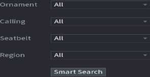
Step2 Select a channel, start time, end time, and set corresponding parameters.
Step3 Click Smart search. The search result is displayed. See Figure 2.99.
For privacy reason, the human face in the image is pixelated.
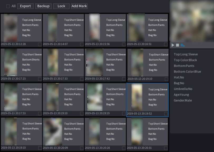
HUMAN BODY DETECTION
Search Results:33
Go To
Figure 2.99
Step4 Select one or multiple results, and then you can to back up the recorded files to the external storage device, select files, click Backup, select the save path and file type, and then click Start.
- To lock the files to make it unable to be overwritten, select the files, and then click Lock.
- To add a mark to the file, select the files and then click Add Mark.
- Go to the Face Properties and Person Details to view detailed information.
Vehicle Detection
You can search according to the vehicle parameters and search the alarm record during the specified period.
This function is for some series products only.
Step1 Select Main Menu ^ AI ^ SMART SEARCH ^ VEHICLE DETECTION.
The VEHICLE DETECTION interface is displayed. See Figure 2.100.
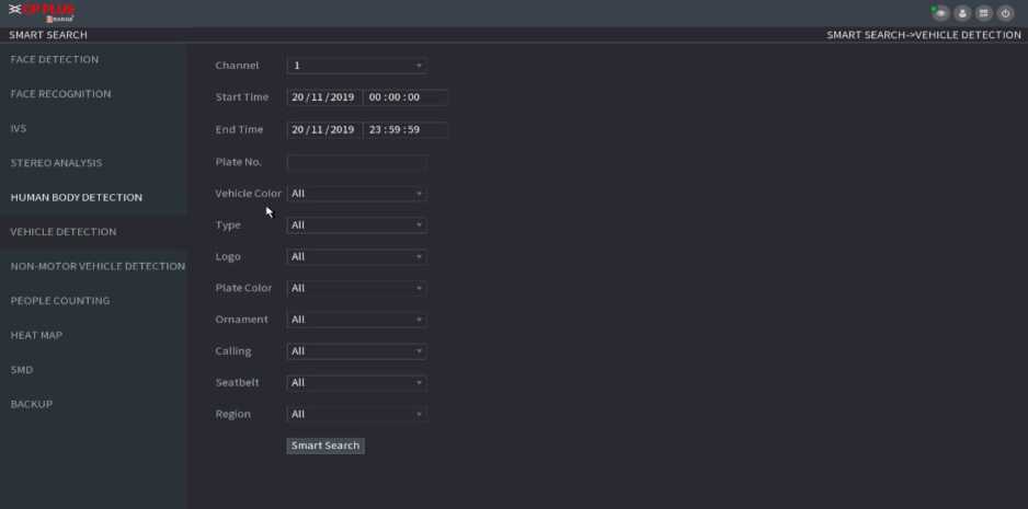
Figure 2.100
Step 2 Select a channel and set parameters.
![]()
- System supports plate fuzzy search.
- System searches all plate numbers by default if you have not set a plate number.
Step3 Click Smart search.
The search result is displayed.
Step4 Select one or multiple results, and then you can:
- To back up the recorded files to the external storage device, select files, click Backup, select the save path and file type, and then click Start.
- To lock the files to make it unable to be overwritten, select the files, and then click Lock.
- To add a mark to the file, select the files and then click Add Mark.
You can search according to the non-motor vehicle parameters and search the alarm record during the specified period.
This function is for some series products only.
Step1 Select Main Menu ■> AI ■> SMART SEARCH ■> NON-MOTOR VEHICLE DETECTION.
The NON-MOTOR VEHICLE DETECTION interface is displayed. See Figure 2.101.
Figure 2.101
Step2 Select the channel and the time, and then select one or multiple features from Type, Vehicle Color, People Number, or Helmet.
Step3 Click Smart Search.
The search result is displayed. See Figure 2.102.
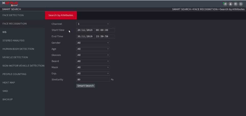
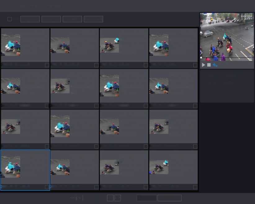
Step4 Select one or multiple results, and then you can:
- To back up the recorded files to the external storage device, select files, click Backup, select the save path and file type, and then click Start.
- To lock the files to make it unable to be overwritten, select the files, and then click Lock.
- To add a mark to the file, select the files and then click Add Mark.
You can detect the peo ple a mo u nt i n the specified zone an d d isplay the statistics i mage.
Step1 Select Main Menu ^ AI ■> SMART SEARCH ^ PEOPLE COUNTING.
The PEOPLE COUNTING interface is displayed. See Figure 2.103.
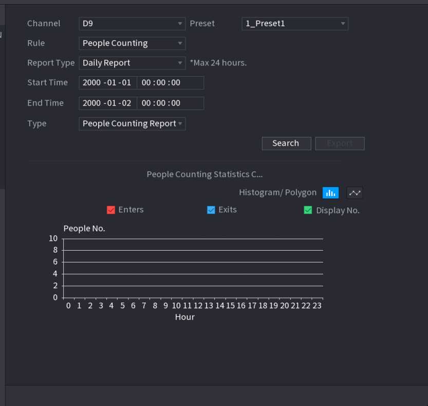
Figure 2.103
Step2 Set parameters such as channel, report type, start time, end time, etc.
| Parameter | Description |
| Channel | Select the channel you want to search people amount. |
| Rule | Select the rule from the dropdown list. |
| Report Type | Select report type from the dropdown list: daily report, monthly report, yearly report. |
| Start time/end time | Set search start time and end time. |
| Type | Select from the dropdown list. |
You can detect the active objects distribution in the monitor zone during the specified period and use different colors to display on the heat map report.
Step1 Select Main Menu ■> AI ■> SMART SEARCH ■> HEAT MAP ■> NORMAL.
The Normal interface is displayed. See Figure 2.104.
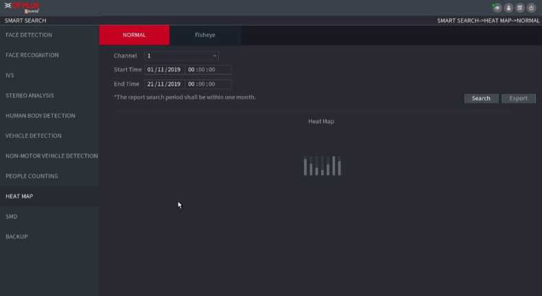
Figure 2.104
Step2 Select channel, start time, end time.
Step3 Click Search.
Step 4 System display heat map report.
Click Export, and then select path. Click Save to save current report to the USB device.
The smart plan is for the smart network camera. It includes IVS, human face detection, human face recognition, human body detection, people counting, heat map. If you do not set a rule here, you cannot use these AI intelligent functions when you are connecting to a smart network camera.
This series NVR products support AI by camera only. Make sure the connected network camera supports intelligent functions. For NVR, it just displays the intelligent alarm information from the smart network camera and set or playback the record file.
Step1 Select Main Menu ^ AI ^ PARAMETERS ^ SMART PLAN. The SMART PLAN interface is displayed. See Figure 2.105.
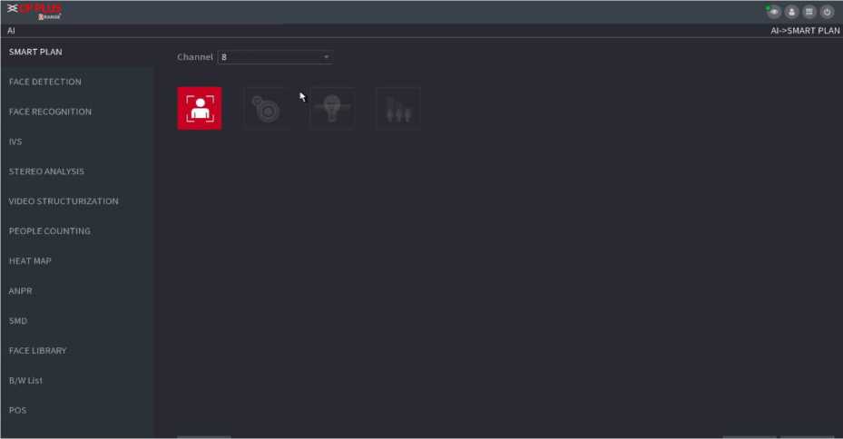
Figure 2.105
Step2 Select a channel number.
System displays different smart plan interfaces since the remote device may supports different functions.
- Select a channel.
- Select a preset.
- Click the smart plan icon at the bottom left. The icon becomes highlighted.
- Click Apply.
Click to
delete the preset.
- Click Add to add a preset.
- Once the remote device does not support preset function, the interface is shown as in Figure 2.106.
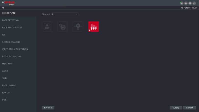
Figure 2.106
The Device can analyze the pictures captured by the camera to detect whether the faces are on the pictures. You can search and filter the recorded videos the faces and play back.
Preparations
The connected camera shall support human face detection function.
Step1 Select Main Menu ^ AI ^ PARAMETERS ^ FACE DETECTION. The FACE DETECTION interface is displayed. See Figure 2.107.
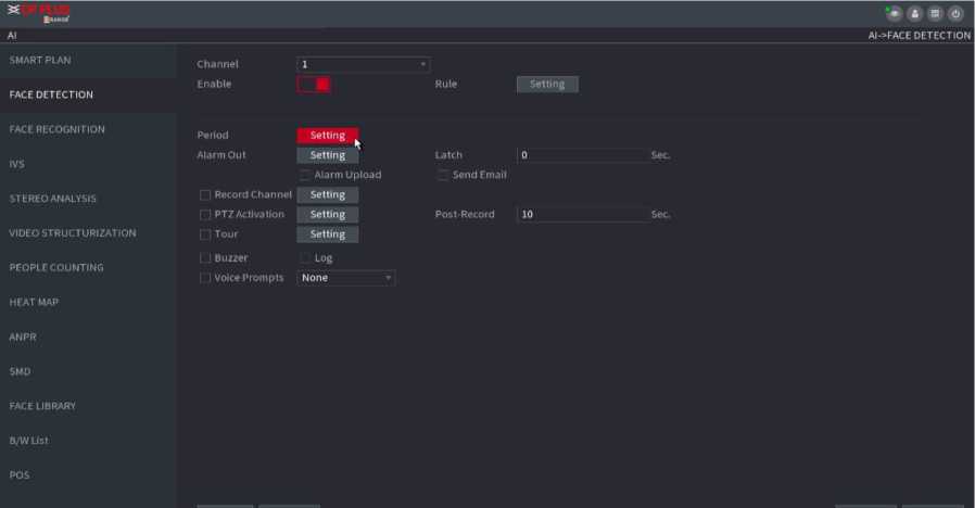
Figure 2.107
Step2 In the Channel list, select a channel that you want to configure face detection function, and then enable it.
Step3 Configure the parameters.
| Parameter | Description |
| Type | This series NVR products support AI by Camera only. AI by Camera means the connected camera does all the AI analytics, and then gives the results to the NVR. |
| Face ROI | Check the box to enable Face ROI function, system displays human face at the enhanced way. |
| Rule | Click Setting to draw areas to filter the target.
You can configure two filtering targets (maximum size and minimum size). When the target is smaller than the minimum size or larger than the maximum size, no alarms will be activated. The maximum size should be larger than the minimum size. Left click to drag the four angles to adjust the size. |
| Period | Configure the period and in the set time range, the corresponding configuration item will be linked to start the alarm. |
| Alarm Out | The alarm device (such as lights, sirens, etc.) is connected to the alarm output port. When an alarm occurs, the NVR device transmits the alarm information to the alarm device. |
| Latch | When the alarm ends, the alarm extended for a period of time. The time range is from 0 seconds to 300 seconds. |
| Alarm
Upload |
Select the check box. When an alarm occurs, the NVR device uploads an alarm signal to the network (including the alarm center). |
| This function is for some series products only. You need to set the alarm | |
| center first. |
| Send Email | Select the check box. When an alarm occurs, the NVR device sends an email to the set mailbox to notify the user.
You need to set the email first. For details, see “4.12.6 Email.“ |
|
| Record
Channel |
Select the check box and select the needed recording channel (support multiple choices). When an alarm occurs, the NVR device activates the channel for recording.
You need to enable intelligent recording and auto recording first. For details, see “4.1.4.6 Schedule.“ |
|
| PTZ Activation | Select the check box and click Setting to select the channel and PTZ action. When an alarm occurs, the NVR device associates the channel to perform the corresponding PTZ action. For example, activate the PTZ in channel one to turn to the preset point X.
Tripwire alarm supports to activate PTZ preset point only. |
|
| You need to set the corresponding PTZ actions first, see “4.4.3 Configuring PTZ | ||
| Functions.“ | ||
| Delay | At the end of the alarm, the recording extends for a period of time. The time range is from 10 seconds to 300 seconds. | |
| Tour | Select the check box and select the channel for tour. When an alarm occurs, the local interface of the NVR device displays the selected channel screen.
You need to set the time interval and mode for tour first, see “4.16.2 Tour.” rm After the tour is over, the preview interface is restored to the screen split mode before the tour. |
|
| Log | Select the check box, the NVR device records the alarm information in the log when an alarm occurs. | |
| Voice
Prompts |
Check the box and then select the corresponding audio file from the dropdown list. System plays the audio file when the alarm occurs. | |
| Buzzer | Select the check box to activate the buzzer when an alarm occurs. | |
Step4 Click Apply to complete the settings.
You can compare the detected faces with the faces in the library to judge if the detected face belongs to the library.
The comparison result will be displayed on the AI mode live view screen and smart search interface and link the alarms.
This series NVR products support AI by camera only.
You can use the connected camera to realize AI function. Make sure the connected camera supports human face detection function.
Step1 Select Main Menu ^ AI ■> PARAMETERS ^ FACE RECOGNITION.
The FACE RECOGNITION interface is displayed. See Figure 2.108.
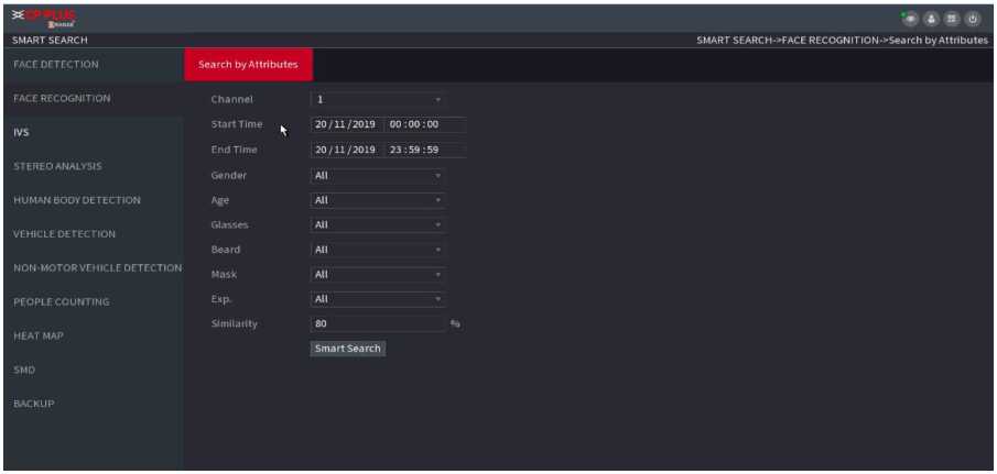
Figure 2.108
Step2 In the Channel list, select a channel that you want to configure face recognition function, and then enable it.
Step3 At Type, system supports AI by Camera only.
Step4 Set parameters.
| Parameter | Description |
| ROI | Check the box to enable ROI function, system displays human face at the enhanced way. |
| Rule | Click Setting to draw areas to filter the target.
You can configure two filtering targets (maximum size and minimum size). When the target is smaller than the minimum size or larger than the maximum size, no alarms will be activated. The maximum size should be larger than the minimum size. Left click to drag the four angles to adjust the size. |
| Period | Configure the period and in the set time range, the corresponding configuration item will be linked to start the alarm. |
| Target Face Database | Click Target Face Database, system displays face database list. Select a database from the dropdown list to compare. |
Step5 Set the Target Face Database.
Step 6 (Optional) Click t2 to modify the similarity. The lower the number is, the easier the alarm linkage will trigger.
Step7 Click to set the alarm linkage.
Step8 Configure the parameters.
| Parameter | Description |
| Period | Configure the period and in the set time range, the corresponding configuration item will be linked to start the alarm. |
| Alarm Out | The alarm device (such as lights, sirens, etc.) is connected to the alarm output port. When an alarm occurs, the NVR device transmits the alarm information to the alarm device. |
| Latch | When the alarm ends, the alarm extended for a period of time. The time range is from 0 seconds to 300 seconds. |
| Alarm
Upload |
Select the check box. When an alarm occurs, the NVR device uploads an alarm signal to the network (including the alarm center). |
| Send Email | Select the check box. When an alarm occurs, the NVR device sends an email to the set mailbox to notify the user. |
| Record
Channel |
Select the check box and select the needed recording channel (support multiple choices). When an alarm occurs, the NVR device activates the channel for recording. |
| PTZ Activation | Select the check box and click Setting to select the channel and PTZ action. When an alarm occurs, the NVR device associates the channel to perform the corresponding PTZ action. For example, activate the PTZ in channel one to turn to the preset point X. |
| Delay | At the end of the alarm, the recording extends for a period of time. The time range is from 10 seconds to 300 seconds. |
| Tour | Select the check box and select the channel for tour. When an alarm occurs, the local interface of the NVR device displays the selected channel screen. |
| After the tour is over, the preview interface is restored to the screen | |
| split mode before the tour. | |
| Log | Select the check box, the NVR device records the alarm information in the log when an alarm occurs. |
| Voice
Prompts |
Check the box and then select the corresponding audio file from the dropdown list. System plays the audio file when the alarm occurs. |
| Buzzer | Select the check box to activate the buzzer when an alarm occurs. |
Step9 Click OK, system goes back to human face recognition interface.
Step10 Click Apply to complete the settings.
2.9.8. IVS (General Behavior Analytics)
The IVS function processes and analyzes the images to extract the key information to match with the specified rules. When the detected behaviors match with the rules, the system activates alarms.
This function is for some series product only. IVS function and human face detection function cannot be valid at the same
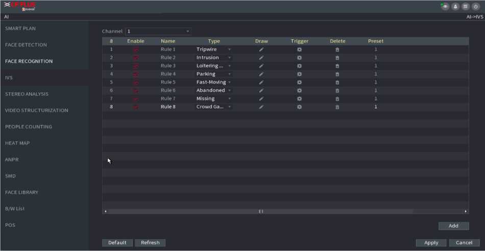
Figure 2.109
Step2 Select a channel from the dropdown list.
Click Add and then set corresponding rule. See Figure 2.110.
Click
to delete the selected rule.
Figure 2.110
Step3 Set corresponding parameters.
Step4 Click Apply.
2.9.8.1.1. Tripwire
When the detection target crosses the warning line along the set direction, the system performs an alarm linkage action.
Stepl Select Main Menu ^ AI ■> PARAMETERS ^ IVS.
In the Type drop-down list, select Tripwire. See Figu re 2. 111.
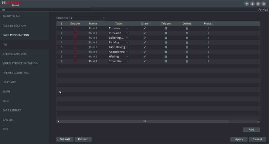
Figure 2.111
Step2 Draw the detection rule. Figure 2.112
Click to draw the rule on the surveillance video, the system displays as Figure 2.112.
Tripwire
01 ffi
Name Rulel
Direction Both
OK
*
- Configure the parameters.
| Parameter | Description | |
| Name | Customize the rule name. | |
| Direction | Set the tripwire direction, including A^B, B^A and A O B. | |
| Click to filter the target. Check the blue wireframe and adjust the | ||
| Filter target | size of the area with the mouse. | |
| Each rule can set 2 target filters (maximum size and minimum size), that is, when the passing target is smaller than the minimum target or larger than the maximum target, no alarm will be generated. The | ||
| maximum size should not be smaller than the minimum size. | ||
| AI
Recognition |
Select AI recognition and the system displays alarm target. The default selection is person and motor vehicle and system
automatically identify the person and motor vehicle appeared within the monitoring range. |
|
| When you select IVS of AI by camera, the connected channel shall | ||
| support tripwire function. | ||
- Press and hold down the left button on the monitor screen to draw the line. The line can be a straight line or a curve.
- Click OK to complete the rule setting.
![]()
Step3 Click
System displays the Trigger interface. See Figure 2.113.
![]()
| SMART PLAN | Channel 1 | ||||||
| FACE DETECTION | 8 Enable | Name | Type | Draw | Trigger | Delete | Preset |
| 1 | Rule 1 | Tripwire • | ß | n | 1 | ||
| 2 | Rule 2 | Intrusion » | ß | B | 1 | ||
| FACE RECOGNITION | Rule 3 | Loitering… • | Ö | s | |||
| IVS | Rule 4 | Parking | s’ | ß | A | 1 | |
| 5 | Rule5 | Fast-Moving • | S | ß | a | 1 | |
| 6 | Rules | Abandoned | >■ | ß | 1 | ||
| STEREO ANALYSIS | 7 | Rule; | Missing ‘ | f | ß | 1 | |
| 8 | Rule8 | Crowd Ga… – | ß | 1 | |||
| VIDEO STRUCTURIZATION | |||||||
| PEOPLE COUNTING | |||||||
| HEAT MAP | |||||||
| AN PR
5 MD FACE LIBRARY |
|||||||
| II1 |
Add
Cancel
Step4 Configure the parameters.
| Parameter | Description |
| Period | Configure the period and in the set time range, the corresponding configuration item will be linked to start the alarm. |
| Alarm Out | The alarm device (such as lights, sirens, etc.) is connected to the alarm output port. When an alarm occurs, the NVR device transmits the alarm information to the alarm device. |
| Latch | When the alarm ends, the alarm extended for a period. The time range is from 0 seconds to 300 seconds. |
| Alarm Upload | Select the check box. When an alarm occurs, the NVR device uploads an alarm signal to the network (including the alarm center). |
| Send Email | Select the check box. When an alarm occurs, the NVR device sends an email to the set mailbox to notify the user. |
| Record
Channel |
Select the check box and select the needed recording channel (support multiple choices). When an alarm occurs, the NVR device activates the channel for recording. |
| PTZ Activation | Select the check box and click Setting to select the channel and PTZ action. When an alarm occurs, the NVR device associates the channel to perform the corresponding PTZ action. For example, activate the PTZ in channel one to turn to the preset point X. |
| Delay | At the end of the alarm, the recording extends for a period of time. The time range is from 10 seconds to 300 seconds. |
| Tour | Select the check box and select the channel for tour. When an alarm occurs, the local interface of the NVR device displays the selected channel screen. |
| Log | Select the check box, the NVR device records the alarm information in the log when an alarm occurs. |
| Voice
Prompts |
Check the box and then select the corresponding audio file from the dropdown list. System plays the audio file when the alarm occurs. |
| Buzzer | Select the check box to activate the buzzer when an alarm occurs. |
Step 5 Click OK to save the alarm setting.
System displays the IVS interface.
Step6 Select the Enable check box and click Apply to complete the tripwire setting.
2.9.8. 1.2. Abandoned Object Detection
System generates an alarm when there is abandoned object in the specified zone.
Stepl In the Type drop-down list, select Abandoned Object.
The interface is shown as Figure 2.114.
Step2 Draw the detection rule.
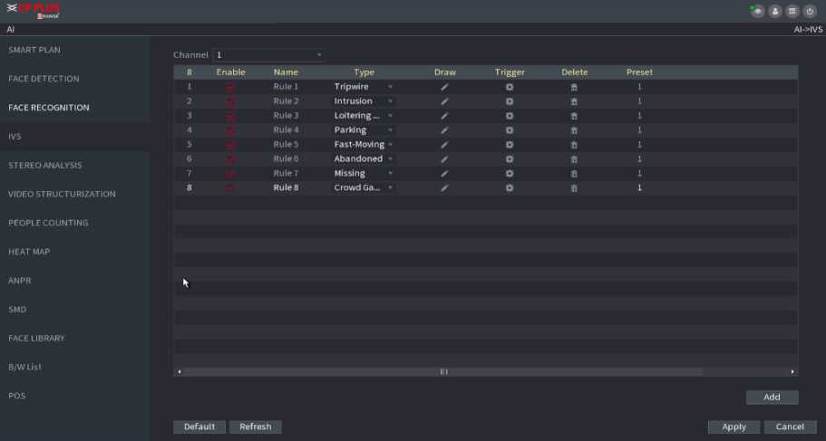
![]()
Figure 2.114
Click
to draw the rule on the surveillance video.
b. Set parameters.
| Parameter | Description |
| Preset | Select a preset you want to use IVS |
| Name | Input customized rule name |
| Duration | System can generate an alarm once the object is in the zone for the specified period. |
| Filter target | Click ES to filter the target. Check the blue wireframe and adjust the size of the area with the mouse. |
- Draw a rule. Left click mouse to draw a zone, until you draw a rectangle, you can right click mouse. ii. Click OK to complete the rule setting.
Step3 Click
![]()
Step4 Click Apply to complete the setup.
-
-
-
-
- Fast moving
-
-
-
You can detect the fast-moving object in the specified zone.
Stepl In the Type drop-down list, select Fast Moving.
The interface is shown as below. See Figure 2.115.
Figure 2.115
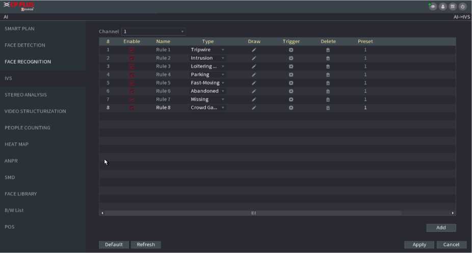
Step2 Draw the detection rule. Figure 2.116
Click to draw the rule on the surveillance video. Set parameters.
| Parameter | Description |
| Preset | Select a preset you want to use IVS |
| Name | Input customized rule name |
| Sensitivity | You can set alarm sensitivity. The value ranges from 1 to 10. The default setup is 5. |
| Filter target | Click □ to filter the target. Check the blue wireframe and adjust the size of the area with the mouse. |
i. Draw a rule. Left click mouse to draw a zone, until you draw a rectangle, you can right click mouse. ii. Click OK to complete the rule setting.
![]()
Step3 Click
Step4 Click Apply to complete the setup.
-
-
-
-
- Crowd Gathering
-
-
-
System can generate an alarm once the people amount gathering in the specified zone is larger than the threshold.
Step1 In the Type drop-down list, select Crowd Gathering Estimation.
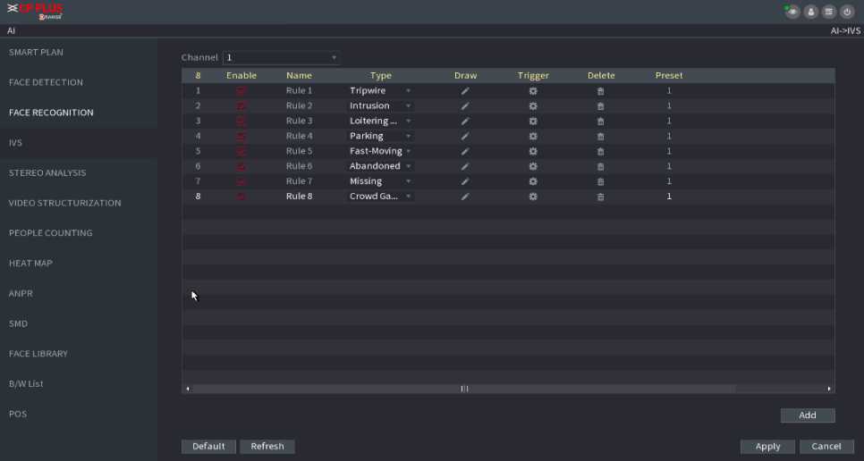
The interface is shown as below. See Figure 2.116.
Figure 2.116
Step2 Draw the detection rule.
![]()
iii.
Click
to draw the rule on the surveillance video.
- Set parameters.
| Parameter | Description |
| Preset | Select a preset you want to use IVS. |
| Name | Input customized rule name |
| Duration | Set the minimum time that the object stays until the alarm is triggered. |
| Filter target | Click □ to filter the target. Check the blue wireframe and adjust the size of the area with the mouse. |
- Draw a rule. Left click mouse to draw a zone, until you draw a rectangle, you can right click mouse.
- Click OK to complete the rule setting.
![]()
Step3 Click
Step4 Click Apply to complete the setup.
2.9.8.1.5. Parking
When the detection target stays in the monitoring area for more than the set duration, the system performs alarm
linkage action.
Stepl In the Type drop-down list, select Parking.
The interface is shown as below. See Figure 2.117.
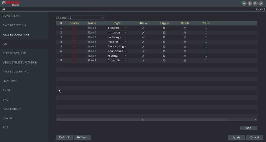
Figure 2.117
Step2 Draw the detection rule.
![]()
vii.
Click
to draw the rule on the surveillance video.
viii. Set parameters.
| Parameter | Description |
| Preset | Set the preset point for IVS detection according to the actual needs. |
| Name | Customize the rule name. |
| Duration | Set the minimum time that the object stays until the alarm is triggered. |
| Filter target | Click DS to filter the target. Check the blue wireframe and adjust the size of the area with the mouse. |
- Draw a rule. Left click mouse to draw a zone, until you draw a rectangle, you can right click mouse.
- Click OK to complete the rule setting.
![]()
Step3 Click
Step4 Click Apply to complete the setup.
-
-
-
-
- Missing Object Detection
-
-
-
System generates an alarm when there is missing object in the specified zone.
Stepl In the Type drop-down list, select Missing Object.
The interface is shown as below. See Figure 2.118

Figure 2.118
Step2 Draw the detection rule. Figure 2.118
![]()
xi.
Click
to draw the rule on the surveillance video.
xii. Set parameters.
| Parameter | Description |
| Preset | Set the preset point for IVS detection according to the actual needs. |
| Name | Customize the rule name. |
| Duration | Set the minimum time that the object stays until the alarm is triggered. |
| Filter target | Click □ to filter the target. Check the blue wireframe and adjust the size of the area with the mouse. |
xiii. Draw a rule. Left click mouse to draw a zone, until you draw a rectangle, you can right click mouse.
xiv. Click OK to complete the rule setting.
![]()
Step3 Click
Step 4 Click Apply to complete the setup.
-
-
-
-
- Loitering Detection
-
-
-
System can generate an alarm once the object is staying in the specified zone longer than the threshold. See Figure 2.119.
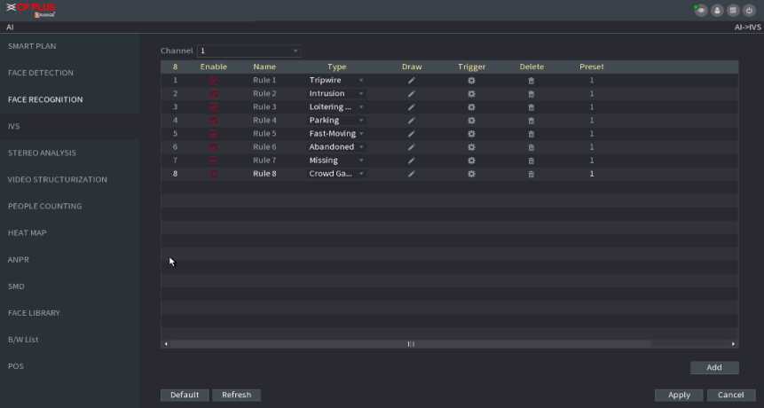
Figure 2.119
Step1 In the Type drop-down list, select Loitering Detection. The interface is shown as below. See Figure 2.119.
Step2 Draw the detection rule. Figure 2.119
![]()
xv.
Click
to draw the rule on the surveillance video.
xvi. Set parameters.
| Parameter | Description |
| Preset | Set the preset point for IVS detection according to the actual needs. |
| Name | Customize the rule name. |
| Duration | Set the minimum time that the object stays until the alarm is triggered. |
| Filter target | Click LJ to filter the target. Check the blue wireframe and adjust the size of the area with the mouse. |
xvii. Draw a rule. Left click mouse to draw a zone, until you draw a rectangle, you can right click mouse. xviii. Click OK to complete the rule setting.
![]()
Step3 Click
Step4 Click Apply to complete the setup.
After set the heat map parameters, go to Main Menu ^ INFO ^ EVENT ^ HEAT MAP to view heat map report.
System uses the video recognition technology to extract the plate number on the surveillance video and then compare it with the specified plate information. System can trigger an alarm once there is a matched result.
You can set different plate recognition rule, alarm linkage actions in different environments (blacklist, whitelist and regular).
Step1 Select Main Menu ^ AI ^ PARAMETERS ^ ANPR. The ANPR interface is displayed. See Figure 2.120.
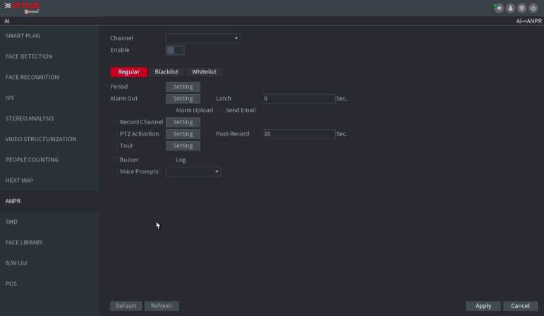
Figure 2.120
Step2 Select the Enable check box to enable ANPR.
Step3 Click Regular (default), Blacklist or Whitelist tab to configure it.
Before activate blacklist alarm or whitelist alarm, you need to add the corresponding plate information.
- Regular: Device triggers an alarm when it detects any plate number.
- Blacklist: Device triggers an alarm when it detects plate number in the blacklist.
- Whitelist: Device triggers an alarm when it detects plate number in the whitelist.
Step4 Set parameters.
| Parameter | Description |
| Configure the period and in the set time range, the corresponding | |
| Period | configuration item will be linked to start the alarm. |
| Alarm Out | The alarm device (such as lights, sirens, etc.) is connected to the alarm output port. When an alarm occurs, the NVR device transmits the alarm information to the alarm device. |
| Latch | When the alarm ends, the alarm extended for a period. The time range is from 0 seconds to 300 seconds. |
| Alarm
Upload |
Select the check box. When an alarm occurs, the NVR device uploads an alarm signal to the network (including the alarm center). |
| Send Email | Select the check box. When an alarm occurs, the NVR device sends an email to the set mailbox to notify the user. |
| Record
Channel |
Select the check box and select the needed recording channel (support multiple choices). When an alarm occurs, the NVR device activates the channel for recording. |
| PTZ Activation | Select the check box and click Setting to select the channel and PTZ action. When an alarm occurs, the NVR device associates the channel to perform the corresponding PTZ action. For example, activate the PTZ in channel one to turn to the preset point X. |
Step5 Click Apply.
You ca n sea rch, view and back up the a la rm i nformation .
Stepl Select Main Menu ^ ALARM ^ ALARM INFO.
The ALARM INFO interface is displayed. See Figure 2.121.
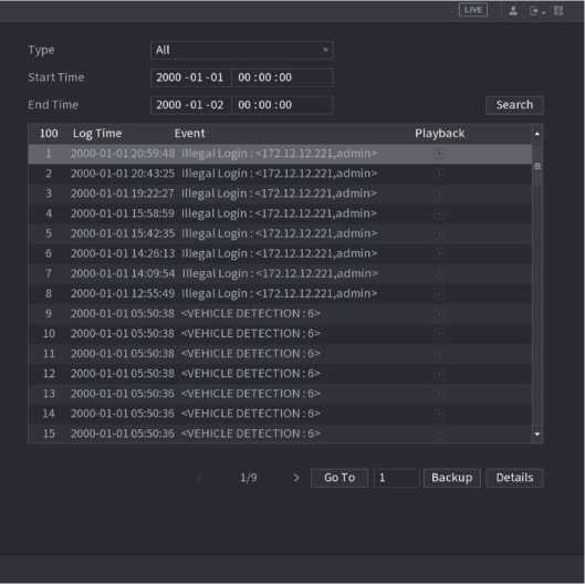
Figure 2.121
Step4 In the Type list, select the event type; In the Start Time box and End Time box, enter the specific time.
Step5 Click Search.
The search results are displayed.
Step6 Click Backup to back up the search results into the external storage device.
![]()
- Select an alarm event log and then click Backup to back up it to peripheral USB device.
- Select an alarm event log, click EOS to play the recorded video of alarm event.
- Double-click a log or click Details to view the detailed information of the event.
You can view NVR alarm event, and remote channel alarm event.
Select Main Menu ■> ALARM ^ ALARM STATUS, the ALARM STATUS interface is displayed. See Figure 2.122.
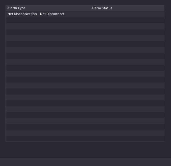
Figure 2.122
Stepl Select Main Menu ^ ALARM ^ ALARM INPUT, The ALARM INPUT interface is displayed. See Figure 2.123.
Step2 There are four alarm types.
- Local alarm: After connecting the alarm device to the NVR alarm input port, system can trigger the corresponding alarm operations when there is alarm signal from the alarm input port to the NVR.
- Network alarm: NVR trigger corresponding alarm operations when it receives the alarm signal via the network transmission.
- IPC external alarm: When the network camera connected peripheral device has triggered an alarm, it can upload the alarm signal to the NVR via the network transmission. The system can trigger the corresponding alarm operations.
- IPC offline alarm: When the network connection between the NVR and the network camera is off, the system can trigger the corresponding alarm operations.
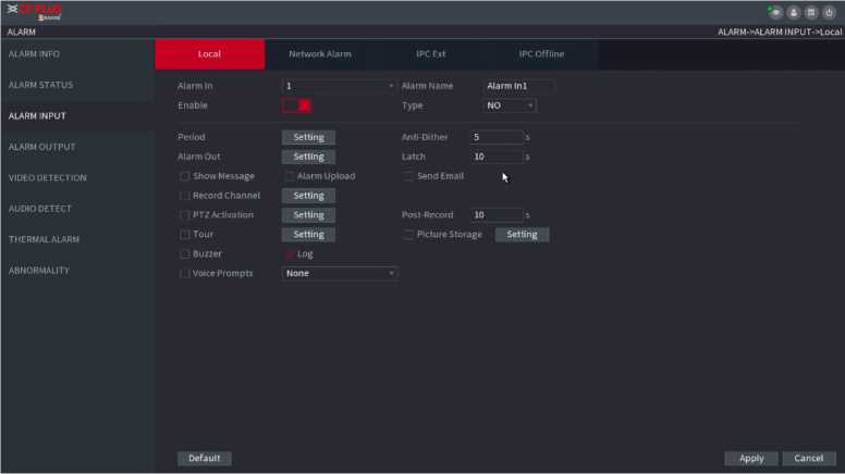
Figure 2.123
Step3 Set Alarm In channel number and then select the Enable check box to enable the function.
Step4 Configure parameters.
| Parameter | Description |
| Alarm in | Select a channel to set alarm. |
| Enable | Check the box to enable the function. |
| Alarm Name | Enter an alarm name. |
| Type | NO (normal open) or NC (normal close). |
| Period | Define a period during which the alarm is active. |
| Alarm Out | The alarm device (such as lights, sirens, etc.) is connected to the alarm output port. When an alarm occurs, the NVR device transmits the alarm information to the alarm device. |
| Latch | When the alarm ends, the alarm extended for a period of time. The time range is from 0 seconds to 300 seconds. |
| Show
Message |
Check box to enable a pop-up message in your local host PC. |
| Alarm Upload | Select the check box. When an alarm occurs, the NVR device uploads an alarm signal to the network (including the alarm center). |
| Send Email | Select the check box. When an alarm occurs, the NVR device sends an email to the set mailbox to notify the user. |
| Record
Channel |
Select the check box and select the needed recording channel (support multiple choices). When an alarm occurs, the NVR device activates the channel for recording. |
| PTZ Activation | Select the check box and click Setting to select the channel and PTZ action. When an alarm occurs, the NVR device associates the channel to perform the corresponding PTZ action. For example, activate the PTZ in channel one to turn to the preset point X. |
| Delay | At the end of the alarm, the recording extends for a period of time. The time range is from 10 seconds to 300 seconds. |
| Tour | Select the check box and select the channel for tour. When an alarm occurs, the local interface of the NVR device displays the selected channel screen |
| Snapshot | Select the Snapshot check box to take a snapshot of the selected channel. |
| Log | Select the check box, the NVR device records the alarm information in the log when an alarm occurs. |
| Voice Prompts | Check the box and then select the corresponding audio file from the dropdown list. System plays the audio file when the alarm occurs. |
| Buzzer | Select the check box to activate the buzzer when an alarm occurs. |
Step5 Click Apply.
You can set proper alarm output (Auto/manual/off). Connect the alarm device to the system alarm output port, and set the mode as auto, system can trigger the corresponding operations when an alarm occurs.
- Auto: Once an alarm event occurs, system can generate an alarm.
- Manual: Alarm device is always on the alarming mode.
- Off: Disable alarm output function.
Step1 Select Main Menu ■> ALARM ■> ALARM OUTPUT.
The ALARM OUTPUT interface is displayed. See Figure 2.124.
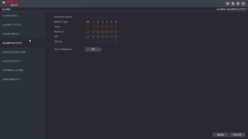
Step2 Select the alarm mode of the alarm output channel.
- Click OK button of the Alarm Release, you can clear all alarm output statuses.
- View the alarm output status on the Status column.
Step3 Click Apply.
The video detection adopts the computer image and graphics process technology. It can analyze the video and check there is considerable changing or not. Once video has changed considerably (such as there is any moving object, video is distorted), system can trigger the corresponding alarm activation operations.
Select Main Menu ■> ALARM ^ VIDEO DETECTION ■> MOTION DETECT, you can see motion detect i nterface. See Figu re 2 . 125. There a re five detection types: motion detection, video loss, tampering, scene changing and PIR alarm.
When the moving object appears and moves fast enough to reach the preset sensitivity value, the system activates the alarm.
Step1 Select Main Menu ^ ALARM ■> VIDIEO DETECTION ^ Motion Detect.
The Motion Detect interface is displayed. See Figure 2.125.
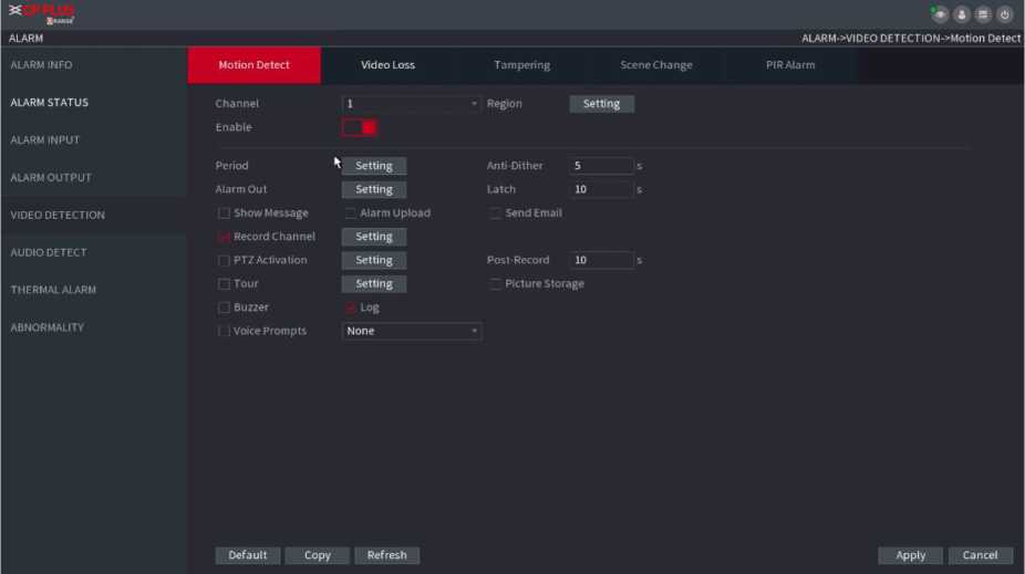
Figure 2.125
Step2 Configure the settings for the motion detection parameters.
| Parameter | Description |
| Channel | In the Channel list, select a channel to set the motion detection. |
| Region | Click Setting to define the motion detection region. |
| Enable MD | Enable or disable the motion detection function. Check the box to enable the function. |
| Period | Define a period during which the motion detection is active. |
| Sensitivity | The higher the value is, the easier it is to trigger an alarm. But at the same time, the false alarm may occur. The default value is recommended. |
| Alarm Out | The alarm device (such as lights, sirens, etc.) is connected to the alarm output port. When an alarm occurs, the NVR device transmits the alarm information to the alarm device. |
| Latch | When the alarm ends, the alarm extended for a period of time. The time range is from 0 seconds to 300 seconds. |
| Show
Message |
Check box to enable a pop-up message in your local host PC. |
| Alarm Upload | Select the check box. When an alarm occurs, the NVR device uploads an alarm signal to the network (including the alarm center). |
| Send Email | Select the check box. When an alarm occurs, the NVR device sends an email to the set mailbox to notify the user. |
| Record
Channel |
Select the check box and select the needed recording channel (support multiple choices). When an alarm occurs, the NVR device activates the channel for recording. |
| PTZ Activation | Select the check box and click Setting to select the channel and PTZ action. When an alarm occurs, the NVR device associates the channel to perform the corresponding PTZ action. For example, activate the PTZ in channel one to turn to the preset point X. |
| Delay | At the end of the alarm, the recording extends for a period of time. The time range is from 10 seconds to 300 seconds. |
| Tour | Select the check box and select the channel for tour. When an alarm occurs, the local interface of the NVR device displays the selected channel screen. |
| Snapshot | Select the Snapshot check box to take a snapshot of the selected channel. |
| Voice Prompts | Check the box and then select the corresponding audio file from the dropdown list. System plays the audio file when the alarm occurs. |
| Buzzer | Select the check box to activate the buzzer when an alarm occurs. |
Step3 Click Apply to save the settings.
• Click Default to restore the default setting.
Click Copy, in the Copy dialog box, select the additional channel(s) that you want to copy the motion detection settings to, and then click Apply.
• Click Test to test the settings.
-
-
-
-
- Setting the Motion Detection Region
-
-
-
Step1 Next to Region, click Setting.
The region setting screen is displayed.
Step2 Point to the middle top of the interface.
The setting interface is displayed. See Figure 2.126.
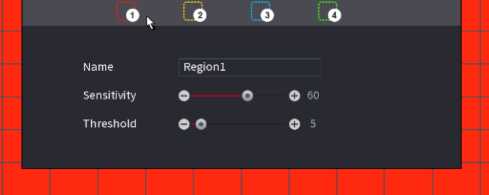
Figure 2.126
Step3 Configure the regions settings. You can configure totally four regions.
a.
Select one region, for example, click
B.
- Drag on the screen to select the region that you want to detect.
- The selected area shows the color that represents the region.
- Configure the parameters.
region belongs to will activate
| Parameter | Description |
| Name | Enter a name for the region. |
| Sensitivity | Every region of every channel has an individual sensitivity value. The bigger the value is, the easier the alarms can be activated. |
| Threshold | Adjust the threshold for motion detect. Every region of every channel has an individual threshold. |
When anyone of the four regions activates motion detect alarm, the channel where this motion detect alarm.
Step4 Right-click on the screen to exit the region setting interface.
Step5 On the Motion Detect interface, click Apply to complete the settings.
-
-
-
-
- Setting Period
-
-
-
![]()
The system only activates the alarm in the defined period.
Stepl Next to Period, click Setting.
The Setting interface is displayed. See Figure 2.127.
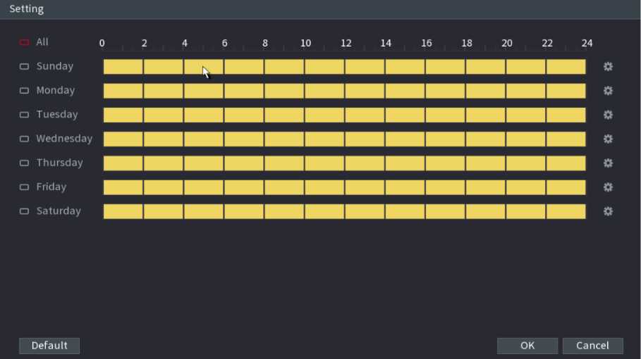
Figure 2.127
Step2 Define the motion detection period. By default, it is active all the time.
• Define the period by drawing.
o Define for a specified day of a week: On the timeline, click the half-hour blocks to select the active period.
![]()
![]()
Define for several days of a week: Click
before each day, the icon switches to
On the timeline
of any selected day, click the half-hour blocks to select the active periods, all the days with s will take
the same settings.
![]()
Define for all days of a week: Click All, all
switches to a. On the timeline of any day, click the half-
hour blocks to select the active periods, all the days will take the same settings.
Define the period by editing. Take Sunday as an example.
![]()
a.
Click
The Period interface is displayed. See Figure 2.128.
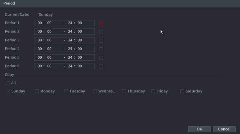
Figure 2.128
o There are six periods for you to set for each day.
o Under Copy, select All to apply the settings to all the days of a week, or select specific day(s) that you want to apply the settings to.
- Click OK to save the settings.
Step3 On the Motion Detect interface, click Apply to complete the settings.
When the camera lens is covered, or the video is displayed in a single color because of sunlight status, the monitoring cannot be continued normally. To avoid such situations, you can configure the tampering alarm settings.
Step1 Select Main Menu ^ ALARM ^ VIDIEO DETECTION ^ Tampering.
The Tampering interface is displayed. See Figure 2.129.
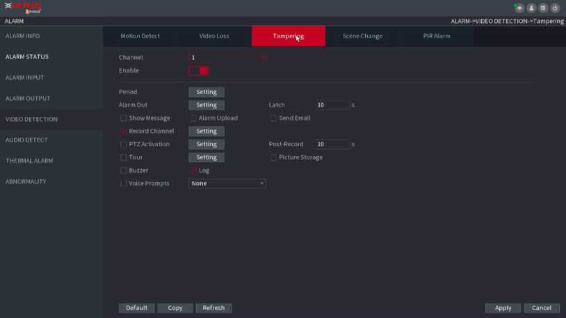
Figure 2.129
Step2 To configure the settings for the tampering detection parameters, see “4.8.5.1 Motion Detect. ” The Tampering function does not have region and sensitivity items.
Step3 Click Apply to complete the settings.
- Click Default to restore the default setting.
- Click Copy, in the Copy dialog box, select the additional channel(s) that you want to copy the motion detection
settings to, and then click Apply.
When the video loss occurs, the system activates the alarm.
Stepl Select Main Menu ^ ALARM ^ VIDIEO DETECTION ^ Video Loss.
The Video Loss interface is displayed. See Figure 2.130.

Figure 2.130
Step 2 To configure the settings for the video loss detection parameters, see “4.8.5.1 Motion Detect.”
The video loss function does not have region and sensitivity items.
Step3 Click Apply to complete the settings.
- Click Default to restore the default setting.
- Click Copy, in the Copy dialog box, select the additional channel(s) that you want to copy the motion detection settings to, and then click Apply.
When the detected scene has changed, system can generate an alarm.
Stepl Select Main Menu ^ ALARM ^ VIDEO DETECTION ^ SCENE CHANGE, The Scene Change interface is displayed. See Figure 2.131.
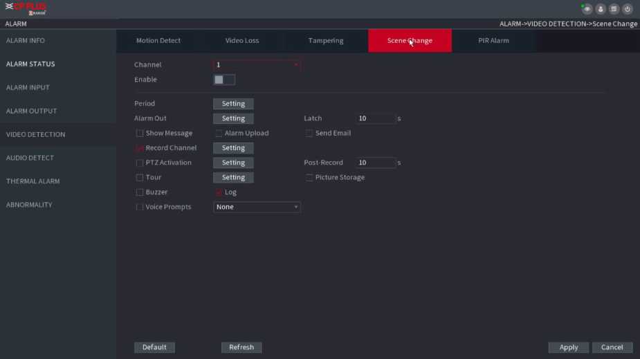
Figure 2.131
Step 2 To configure the settings for the scene change parameters, see “4.8.5.1 Motion Detect.” The scene change function does not have region and sensitivity items.
Step3 Click Apply to complete the settings.
- Click Default to restore the default setting.
- Click Copy, in the Copy dialog box, select the additional channel(s) that you want to copy the motion detection
settings to, and then click Apply.
When the detected scene has changed, system can generate an alarm. PIR function helps enhancing the accuracy and validity of motion detect. It can filter the meaningless alarms that are activated by the objects such as falling leaves, flies. The detection range by PIR is smaller than the field angle.
PIR function is enabled by default if it is supported by the cameras. Enabling PIR function will get the motion detect to be enabled automatically to generate motion detection alarms; if the PIR function is not enabled, the motion detect just has the general effect.
Stepl Select Main Menu ^ ALARM ^ VIDEO DETECT ^ PIR ALARM. The PIR Alarm interface is displayed. See Figure 2.132.
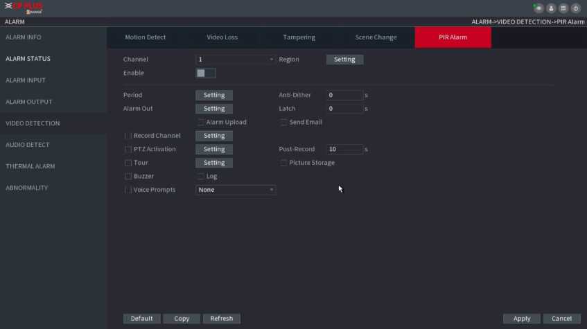
Figure 2.132
Step2 To configure the settings for the PIR alarm parameters, see “4.8.5.1 Motion Detect.”
Step3 Click Apply to complete the settings.
- Click Default to restore the default setting.
- Click Copy, in the Copy dialog box, select the additional channel(s) that you want to copy the motion detection settings to, and then click Apply.
System can generate an alarm once it detects the audio is not clear, the tone color has changed or there is abnormal or audio volume changes.
Step1 Select Main Menu ^ ALARM ■> AUDIO DETECT. The AUDIO DETECT interface is displayed. See Figure 2.133.
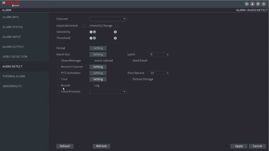
Figure 2.133
| Parameter | Description |
| Channel | In the Channel list, select a channel to set. |
| Input abnormal | Check the box here, system can generate an alarm once the audio input is abnormal. |
| Intensity change | Check the box here, system can generate an alarm once the audio volume becomes strong. |
| Period | Define a period during which the function is active. |
| Sensitivity | The higher the value is, the easier it is to trigger an alarm. But at the same time, the false alarm may occur. The default value is recommended. |
| Threshold | You can set intensity change threshold. The smaller the value is, the higher to sensitivity is. |
| Alarm Out | The alarm device (such as lights, sirens, etc.) is connected to the alarm output port. When an alarm occurs, the NVR device transmits the alarm information to the alarm device. |
| Latch | When the alarm ends, the alarm extended for a period of time. The time range is from 0 seconds to 300 seconds. |
| Show
Message |
Check box to enable a pop-up message in your local host PC. |
Select the check box. When an alarm occurs, the NVR device uploads an alarm signal to the network (including the alarm center).
Alarm Upload
| Send Email | Select the check box. When an alarm occurs, the NVR device sends an email to the set mailbox to notify the user. |
| Record Channel | Select the check box and select the needed recording channel (support multiple choices). When an alarm occurs, the NVR device activates the channel for recording. |
| PTZ Activation | Select the check box and click Setting to select the channel and PTZ action. When an alarm occurs, the NVR device associates the channel to perform the corresponding PTZ action. For example, activate the PTZ in channel one to turn to the preset point X. |
| Delay | At the end of the alarm, the recording extends for a period of time. The time range is from 10 seconds to 300 seconds. |
| Tour | Select the check box and select the channel for tour. When an alarm occurs, the local interface of the NVR device displays the selected channel screen. |
| Snapshot | Select the Snapshot check box to take a snapshot of the selected channel. |
| Log | Select the check box, the NVR device records the alarm information in the log when an alarm occurs. |
| Voice Prompts | Check the box and then select the corresponding audio file from the dropdown list. System plays the audio file when the alarm occurs. |
| Buzzer | Select the check box to activate the buzzer when an alarm occurs. |
Step3 Click Apply to complete the settings.
System supports thermal devices and receives the alarm signal from it. It can recognize the alarm type, and then trigger the corresponding alarm actions.
The system supports fire alarm, temperature (temperature difference) and cold/hot alarm.
Fire alarm: System generates an alarm once it detects there is a fire. The alarm mode includes Preset and Excluded zone.
Temperature (temperature difference) : System triggers an alarm once the temperature difference between two positions is higher or below the specified threshold.
Clod/hot alarm: System triggers an alarm once the detected position temperature is higher or below the specified threshold.
- The connected channel shall support temperature test function.
- This function is for some series products only. It supports enable/disable function only. Go to the front-end device to set corresponding parameters.
Step1 Select Main Menu ^ ALARM ^ THERMAL ALARM. The THERMAL ALARM interface is displayed. See Figure 2.134.
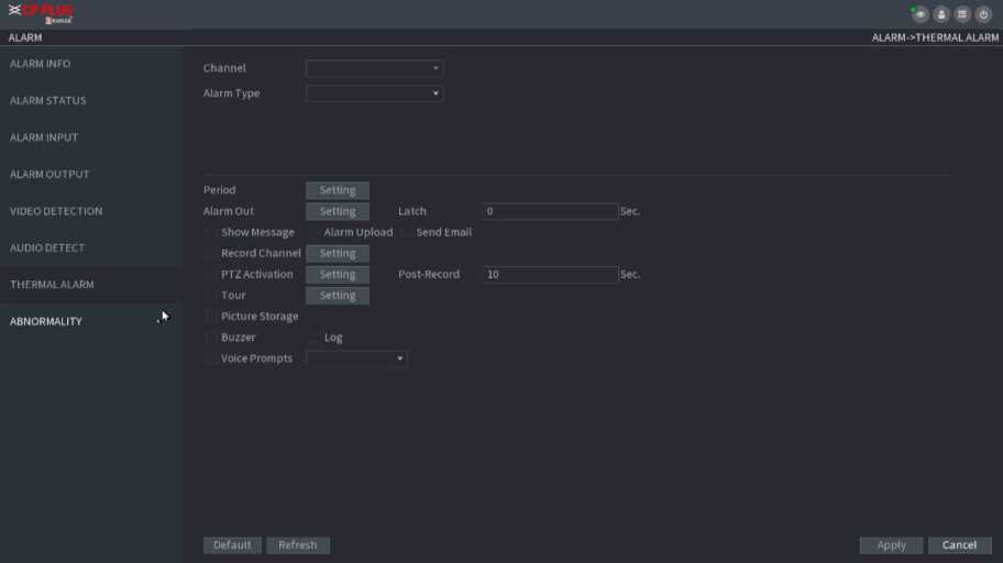
Figure 2.134
Step2 Select a channel and alarm type, enable the thermal alarm function.
Step3 Select fire mode and then enable this function (If the alarm type is Fire Alarm). System supports preset mode and zone excluded mode.
Preset: Select a preset and then enable the function. System generates an alarm once it detects there is a fire.
Global: System filters the specified high temperature zone. System generates an alarm once the rest zone has fire.
Step4 Set parameters.
| Parameter | Description |
| Alarm Out | The alarm device (such as lights, sirens, etc.) is connected to the alarm output port. When an alarm occurs, the NVR device transmits the alarm information to the alarm device. |
| Latch | When the alarm ends, the alarm extended for a period of time. The time range is from 0 seconds to 300 seconds. |
| Show
Message |
Check box to enable a pop-up message in your local host PC. |
| Alarm Upload | Select the check box. When an alarm occurs, the NVR device uploads an alarm signal to the network (including the alarm center). |
| Send Email | Select the check box. When an alarm occurs, the NVR device sends an email to the set mailbox to notify the user. |
| Record
Channel |
Select the check box and select the needed recording channel (support multiple choices). When an alarm occurs, the NVR device activates the channel for recording. |
| PTZ Activation | Select the check box and click Setting to select the channel and PTZ action. When an alarm occurs, the NVR device associates the channel to perform the corresponding PTZ action. For example, activate the PTZ in channel one to turn to the preset point X. |
| Delay | At the end of the alarm, the recording extends for a period of time. The time range is from 10 seconds to 300 seconds. |
| Tour | Select the check box and select the channel for tour. When an alarm occurs, the local interface of the NVR device displays the selected channel screen. |
| Snapshot | Select the Snapshot check box to take a snapshot of the selected channel. |
| Log | Select the check box, the NVR device records the alarm information in the log when an alarm occurs. |
| Voice Prompts | Check the box and then select the corresponding audio file from the dropdown list. System plays the audio file when the alarm occurs. |
| Buzzer | Select the check box to activate the buzzer when an alarm occurs. |
Step5 Click Apply.
Stepl Select Main Menu ^ ALARM ^ ABNORMALITY. The Abnormality interface is displayed. See Figure 2.135.
Figure 2.136
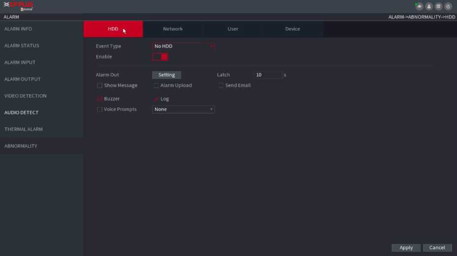
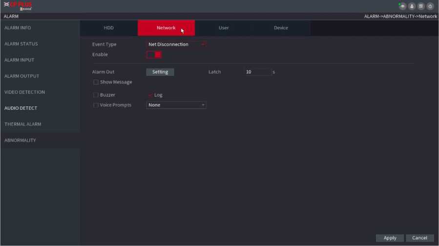
Figure 2.138
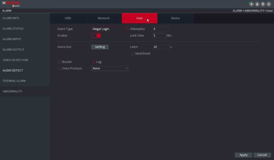
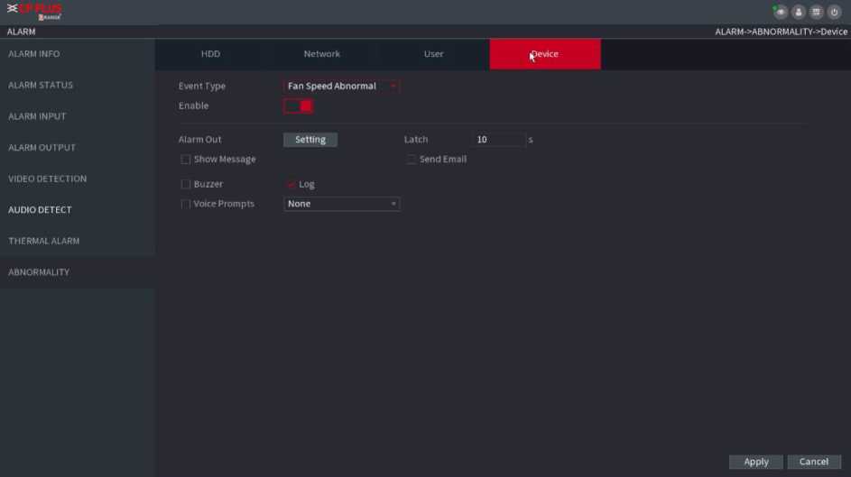
| Parameter | Description |
| Event Type | Click the corresponding tab to set different abnormality events.
HDD: Sets process method when there is a HDD event such as HDD error, no HDD, no space. See Figure Figure 2.135. Network: Sets process method when there is a network event such as disconnection, IP conflict, MAC conflict. See Figure Figure 2.136. User: Sets process method when there is an Illegal login event Figure 2.137. Device: Sets process method when fan speed is abnormal, or there is a network security event. See Figure 2.138. |
| Enable | Check the box to enable the function |
| Less than | System generates an alarm once the HDD space is less than the threshold. |
| Attempts | Set the maximum number of allowable wrong password entries. The account will be locked after your entries exceed the maximum number. |
| Lock Time | Set how long the account is locked for. The value ranges from 1 minute to 60 minutes. |
| Alarm Out | The alarm device (such as lights, sirens, etc.) is connected to the alarm output port. When an alarm occurs, the NVR device transmits the alarm information to the alarm device. |
| Latch | When the alarm ends, the alarm extended for a period of time. The time range is from 0 seconds to 300 seconds. |
| Show
Message |
Check box to enable a pop-up message in your local host PC. |
| Alarm Upload | Select the check box. When an alarm occurs, the NVR device uploads an alarm signal to the network (including the alarm center). |
| Send Email | Select the check box. When an alarm occurs, the NVR device sends an email to the set mailbox to notify the user. |
| Record Channel | Select the check box and select the needed recording channel (support multiple choices). When an alarm occurs, the NVR device activates the channel for recording. |
| PTZ Activation | Select the check box and click Setting to select the channel and PTZ action. When an alarm occurs, the NVR device associates the channel to perform the corresponding PTZ action. For example, activate the PTZ in channel one to turn to the preset point X. |
| Delay | At the end of the alarm, the recording extends for a period of time. The time range is from 10 seconds to 300 seconds. |
| Tour | Select the check box and select the channel for tour. When an alarm occurs, the local interface of the NVR device displays the selected channel screen. |
| Snapshot | Select the Snapshot check box to take a snapshot of the selected channel. |
| Log | Select the check box, the NVR device records the alarm information in the log when an alarm occurs. |
| Voice Prompts | Check the box and then select the corresponding audio file from the dropdown list. System plays the audio file when the alarm occurs. |
| Buzzer | Select the check box to activate the buzzer when an alarm occurs. |
Step3 Click Apply.
You can connect the Device to the POS (Point of Sale) machine and receive the information from it. This function applies to the scenarios such as supermarket POS machine. After connection is established, the Device can access the POS information and display the overlaid text in the channel window.
Playing POS information in the local playback and viewing the POS information in the live view screen support single channel mode and four-channel mode. Displaying monitoring screen and playing back in the web support multi-channe
The system supports fuzzy search.
Step1 Select Main Menu ^ POS ■> POS SEARCH.
The POS SEARCH interface is displayed. See Figure 2.139.
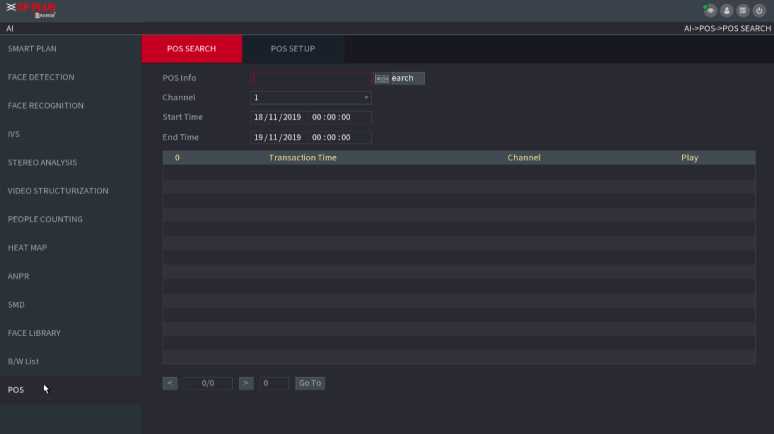
Step2 In the POS SEARCH box, enter the information such as transaction number on your receipt, amount, or product name.
Step4 In the Start Time box and End Time box, enter the time period that you want to search the POS transaction information.
Step5 Click Search. The searched transaction results display in the table.
Step1 Select Main Menu > POS > POS SETUP. The POS SETUP interface is displayed. See Figure 2.140
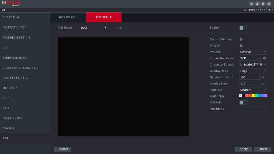
Figure 2.140
Step2 Configure the settings for the POS parameters.
| Parameter | Description |
| POS Name | In the POS Name list, select the POS machine that you want n
to configure settings for. Click KM to modify the POS name.
|
| Enable | Enable the POS function. |
| Record CH | Click ^3 to select a channel to record. |
| Privacy Setup | Enter the privacy contents. |
| Protocol Type | Select POS by default. Different machine corresponds to different protocol. |
| Connect Type | In the Connect Type list, select the connection protocol type.
Click ^3, the IP Address interface is displayed. In the Source IP box, enter the IP address (the machine that is connected to the Device) that sends messages. |
| Convert | Select a character encoding mode. |
| n I
Overlay |
In the Overlay list, Select Turn or ROLL.
Turn: Once the information is at 16 lines, system displays the next page. ROLL: Once the information is at 16 lines, system rolls one line after another to delete the first line. When the local preview mode is in 4-split, the turn/ROLL function is based on 8 lines. |
| Network time out | When the network is not working correctly and cannot be recovered after the entered timeout limit, the POS information will not display normally. After the network is recovered, the latest POS information will be displayed. |
| Time Display | Enter the time that how long you want to keep the POS information displaying. For example, enter 5, the POS information disappear from the screen after 5 seconds. |
| Font Size | In the Font Size list, select Small, Medium, or Big as the text size of POS information |
| COLOR | In the color bar, click to select the color for the text size of |
| POS Info | Enable the POS Info function, the POS information displays in the live view/WEB. |
| Line Delimiter | There is no line delimiter by default.
After set the line delimiter (HEX), the overlay information after the delimiter is displayed in the new line. For example, the line delimiter is F and the overlay information is 123156789, NVR displays overlay information on the local preview interface and Web as:1236789 |
Step3 Click Apply to complete the settings.
Stepl Click Setup, The Privacy interface is displayed. See Figure 2.141.
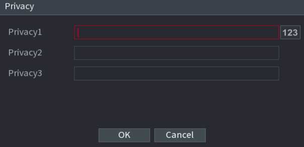
Figure 2.141
Step2 Set privacy information.
Step3 Click OK button.
Connection type is UDP or TCP.
Stepl Select Connect Type as UDP, TCP_CLINET or TCP.
![]()
Step2 Click
The IP Address interface is displayed. See Figure 2.142.
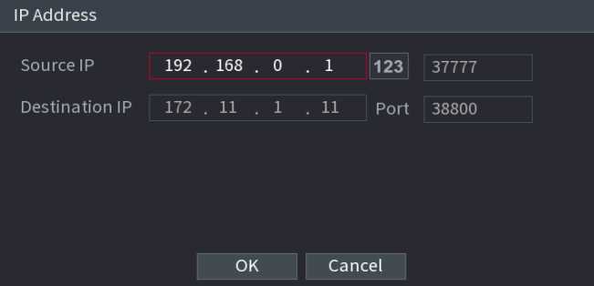
Figure 2.142
Step3 Source IP and Port. Refers to POS IP address and port.
Step4 Click OK to complete setup.
You ca n view a nd sea rch the log i nformation, or backu p log to the USB device.
Stepl Select Main Menu ^ OPERATION ^ LOG, The LOG interface is displayed. See Figure 2.143.
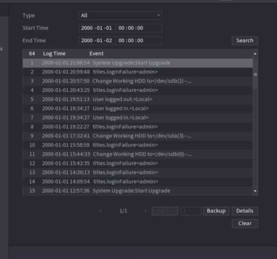
Figure 2.143
Step5 In the Type list, select the log type that you want to view (System, Config, Storage, Record,
Account, Clear, Playback, and Connection) or select All to view all logs.
Step6 In the Start Time box and End Time box, enter the time period to search, and then click.
The search results are displayed. See Figure 2.144.
| Type | All | ||
| Start Time | 2018 -01 -30 | 00 :00 :00 | |
| End Time | 2018 -01 -31 | 00:00:00 | Search |
39 Log Time Event
| 25 | 2018-01-30 14:51:11 | Save <NETWORK> config! | |
| 26 | 2018-01-30 14:51:21 | HDD Amount<1>, Current Working HDD… | |
| 27 | 2018-01-30 14:51:22 | Save <P2P> config! | |
| 28 | 2018-01-30 14:51:22 | Save <P2P> config! | |
| 29 | 2018-01-30 14:51:31 | Save <PIR Alarm> config! | |
| 30 | 2018-01-30 14:51:56 | S.M.A.R.TINFO | |
| 31 | 2018-01-30 14:51:56 | S.M.A.R.TINFO | |
| 32 | 2018-01-30 14:52:31 | Add Group<admin> | |
| 33 | 2018-01-30 14:52:31 | Add Group<user> | |
| 34 | 2018-01-30 14:52:31 | Add User<Onvif:admin> | |
| 35 | 2018-01-30 14:52:31 | User logged in.<admin> | |
| 36 | 2018-01-30 14:52:35 | Save <GENERAL> config! | |
| 37 | 2018-01-30 14:52:36 | Save <NETWORK> config! | |
| 38 | 2018-01-30 14:52:39 | Save <GENERAL> config! | |
| 39 | 2018 01 30 14 53:10 | User logged in.< 127.0.0.1> |
Backup Details
Clear
Figure 2.144
Click Details or double-click the log that you want to view, the Detailed Information interface is displayed. Click Next or Previous to view more log information.
- Click Backup to back up the logs into the USB storage device.
- Click Clear to remove all logs.
Select Main Menu ^ SYSTEM ^ VERSION, you can go to VERSION interface. You can view NVR version information. Slightly different may be found on the user interface.
You can view the HDD quantity, HDD type, total space, free space, status, and S.M.A.R.T information.
Select Main Menu ^ OPERATION ^ INFOMATION ^ HDD, the HDD interface is displayed. See Figure 2.145.
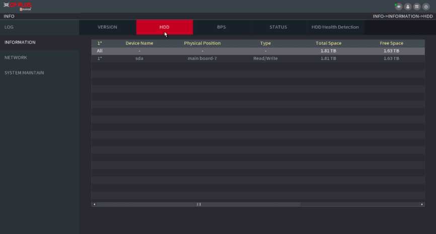
Figure 2.145
Here is for you to view current video bit rate (kb/s) and resolution.
Select Main Menu ^ OPERATION ^ INFOMATION ^ BPS, the BPS interface is displayed. See Figure 2.146.
![]()
| LOG | VERSION | HDD | ^BPS | STATUS | HDD Health Detection | ||
| C ho n | nelKb/S | Resolution Wave | |||||
| INFORMATION | |||||||
| 1 | 2037 | 1280*960 | k | ||||
| NETWORK | 2 | 0 | 352*288 | L | |||
| 3 | 0 | L | |||||
| SYSTEM MAINTAIN | 4 | 0 | — | L | |||
| 5 | 0 | L | |||||
| 6 | 0 | L | |||||
| 7 | 0 | L | |||||
| 8 | 2346 | 1280*960 | k | ||||
| 9 | 0 | — | L | ||||
| 10 | 0 | L | |||||
| 11 | 0 | — | L | ||||
| 12 | 0 | — | l | ||||
| 13 | 0 | — | L | 1 | |||
| 14 | 0 | — | L | [ | |||
| 15 | 2064 | 1280*960 | k | [ | |||
| 16 | 0 | — | L | [ | |||
Figure 2.146
You can view fan running status such as speed, CPU temperature, and memory.
Select Main Menu ^ OPERATION ^ INFOMATION ^ Status, the Status interface is displayed. See
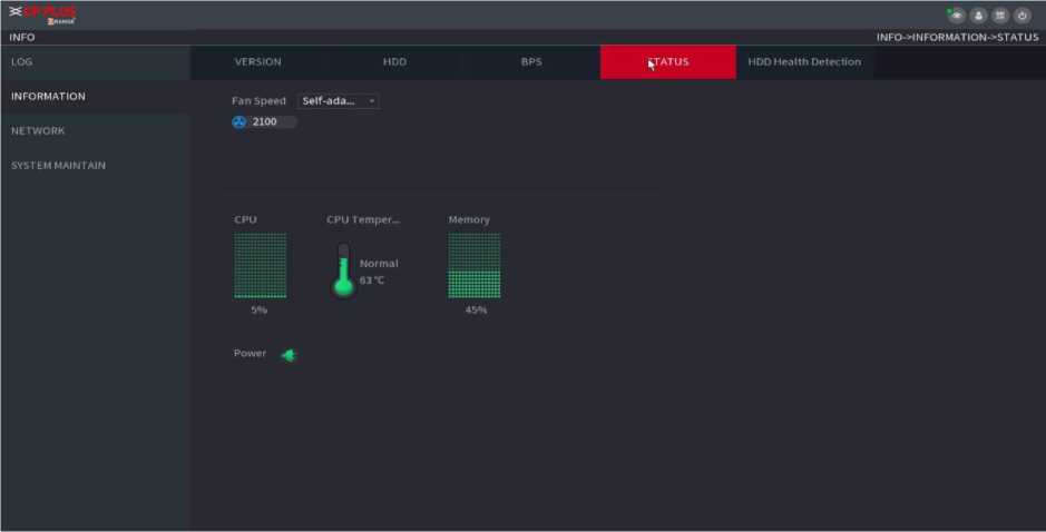
Figure 2.147
You can view HDD health status. System supports Seagate SKYHAWK series 4T and higher HDD. It displays HDD name,
space, manufacturer, Serial No., and health status.
Stepl Select Main Menu ^ OPERATION ^ INFOMATION ^ HDD Health Detection.
The HDD Health Detection interface is displayed. See Figure 2.148.
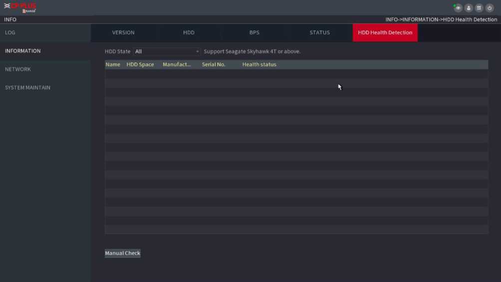
Figure 2.148
Step2 Double-click the HDD in the list, system displays the detection report.
Step3 Select an item in the list, system displays the corresponding report. System displays the curve report of the recent week by default.
ŒJ
You can view the online user information or block any user for a period of time. To block an online user, click and then enter the time that you want to block this user. The maximum value you can set is 65535.
The system detects every 5 seconds to check whether there is any user added or deleted and update the user list timely.
Select Main Menu ■> OPERATION ■> NETWORK ■> ONLINE USERS, the Online Users interface is displayed. See Figure 2.149.
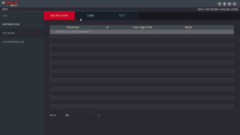
Figure 2.149
Network load means the data flow which measures the transmission capability. You can view the information such as data receiving speed and sending speed.
Step1 Select Main Menu ^ INFO ^ NETWORK ^ LOAD. The LOAD interface is displayed. See Figure 2.150.
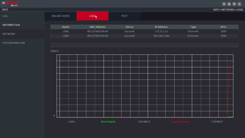
Figure 2.150
Step2 Click the LAN name that you want to view, for example, LAN1.
The system displays the information of data sending speed and receiving speed.
System displays LAN1 load by default.
Only one LAN load can be displayed at one time.
You ca n test the network con nection status betwee n the Device a n d other devices.
Stepl Select Main Menu ^ INFO ^ NETWORK ^ TEST. The TEST interface is displayed. See Figure 2.151.
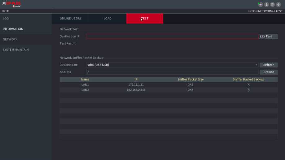
Figure 2.151
Step2 In the Destination IP box, enter the IP address.
Step3 Click Test.
After testing is completed, the test result is displayed. You can check the evaluation for average delay, packet loss, and network status.
When the Device has been running for a long time, you can configure the auto reboot when the Device is not working. You can also configure the case fan mode to reduce noise and extend the service life.
Stepl Select Main Menu ^ OPERATION ■> SYSTEM MAINTAIN ^ AUTO MAINTAIN. The AUTO MAINTAIN interface is displayed. See Figure 2.152.
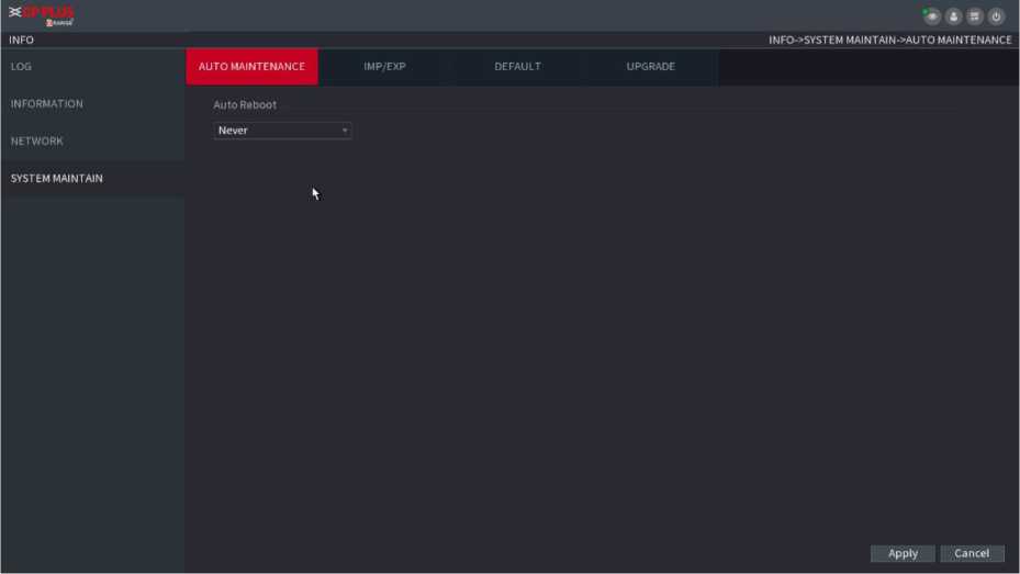
Figure 2.152
Step4 Configure the settings for the system maintenance parameters.
| Parameter | Description |
| Auto Reboot | In the Auto Reboot list, select the reboot time. |
| Case Fan Mode | In the Case Fan Mode list, you can select Always run or Auto. If you select Auto, the case fan will stop or start according to the external conditions such as the Device
temperature. |
Step5 Click Apply to complete the settings.
You can export or import the Device system settings if there are several Devices that require the same setup.
![]()
The IMP/EXP interface cannot be opened if the backup operation is ongoing on the other interfaces. When you open the IMP/EXP interface, the system refreshes the devices and sets the current directory as the first root directory. Click Formal to format the USB storage device.
Step1 Select Main Menu ^ OPERATION ^ SYSTEM MAITAIN ^ IMP/EXP. The IMP/EXP interfaceis displayed. See Figure 2.153.
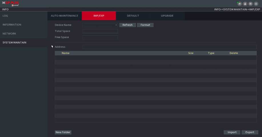
Figure 2.153
Step2 Insert a USB storage device into one of the USB ports on the Device.
Step3 Click Refresh to refresh the interface.
The connected USB storage device is displayed. See Figure 2.154.
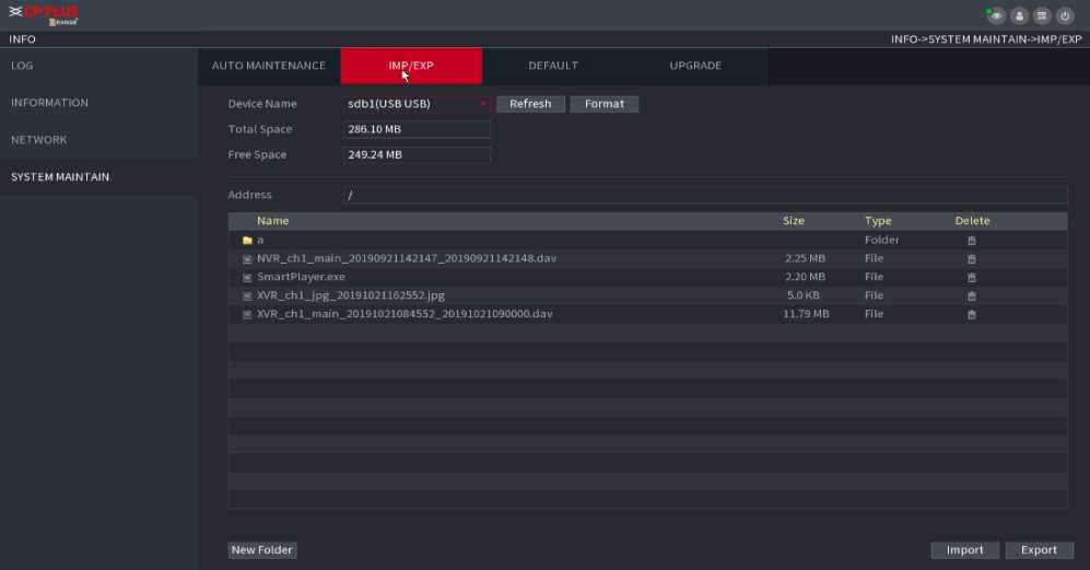
Figure 2.154
There is a folder under the name style of “Config_[YYYYMMDDhhmmss]”. Double-click this folder to view the backup files.
![]()
This function is for admin account only.
You can select the setti ngs that you wa nt to restore to the factory defa u lt.
Stepl Select Main Menu ^ OPERATION ^ SYSTEM MAITAIN ^ DEFAULT.
The DEFAULT interface is displayed. See Figure 2.155.
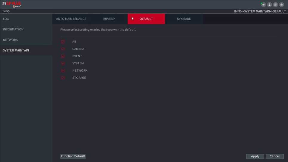
Figure 2.155
Select the settings that you want to restore, and then click Apply. The system starts restoring the selected settings. Click Factory Default, and then click OK. The system starts restoring the whole settings.
Stepl Insert a USB storage device containing the upgrade files into the USB port of the Device.
Step2 Select Main Menu ^ OPERATION ^ SYSTEM MAINTAIN ^ UPGRADE.
The UPGRADE interface is displayed. See Figure 2.156.
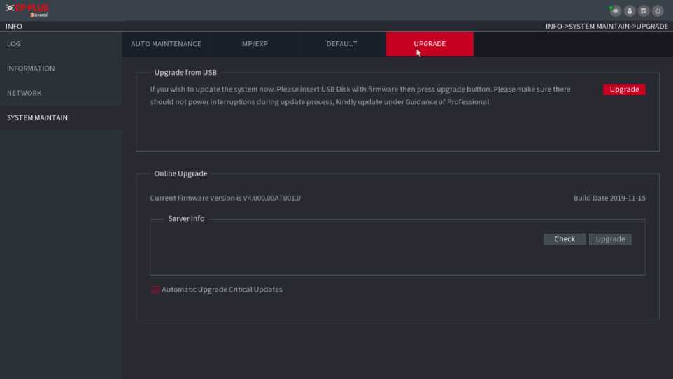
Figure 2.156
The System Upgrade interface is displayed. See Figure 2.157.
Browse
| Device Name | sdbl(USBUSB) | Refresh Format |
| Total Space | 286.10 MB | |
| Free Space | 249.24 MB |
Address
| Name | Size | Type | Delete |
| k a | Folder | B | |
| ® NVR_chl_main_20190921142147_2… | 2.25 MB | Filj^ | |
| g SmartPlayer.exe | 2.20 MB | File | B |
| ® XVR_chl_jpg_20191021162552.jpg | 5.0 KB | File | B |
| a XVR_chl_main_20191021084552_2… | 11.79 MB | File | n |
File Name
OK Cancel
Step4 Click the file that you want to upgrade.
The selected file is displayed in the Update File box.
Step5 Click Start.
-
-
-
-
- Online Upgrade
-
-
-
When the Device is connected to Internet, you can use online upgrade function to upgrade the system. Before using this function, you need to check whether there is any new version by auto check or manual check.
- Auto check: The Device checks if there is any new version available at intervals.
- Manual check: Perform real-time check whether there is any new version available.

Ensure the correct power supply and network connection during upgrading; otherwise the upgrading might be failed.
Step1 Select Main Menu ^ OPERATION ^ SYSTEM MAINTAIN ^ UPGRADE.
The UPGRADE interface is displayed. See Figure 2.158.
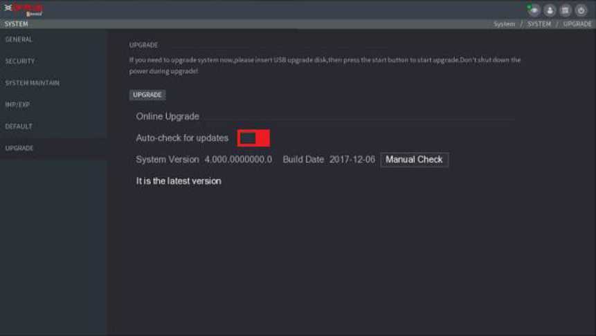
Figure 2.158
Step2 Check whether there is any new version available.
- Auto-check for updates: Enable Auto-check for updates.
- Manual check: Click Manual Check, the system starts checking the new versions. After checking is completed, the check result is displayed.
- If the “It is the latest version” text is displayed, you do not need to upgrade.
- If the text indicating there is a new version, go to the step 3.
Step3 Click Upgrade now to update the system.
-
-
-
-
- Uboot Upgrading
-
-
-

- Under the root directory in the USB storage device, there must be “u-boot.bin.img” file and “update.img” file saved, and the USB storage device must be in FAT32 format.
- Make sure the USB storage device is inserted; otherwise the upgrading cannot be performed.
When starting the Device, the system automatically checks whether there is a USB storage device connected and if there is any upgrade file, and if yes and the check result of the upgrade file is correct, the system will upgrade automatically. The Uboot upgrade can avoid the situation that you have to upgrade through +TFTP when the Device is halted.
You can back up the record file to the UBS device.
Step1 Connect USB burner, USB device or portable HDD to the device.
Step2 Select Main Menu ^ BACKUP, the Backup interface is displayed. See Figure 2.159
| Device Name | sdal(USB USB) | Format | 1.37 GB/14.83 GB(Free/Total) |
| Path | Browse | ||
| Record C… | DI | ||
| Type | All | Main Stream | |
| Start Time | 2000 -01 -01 00:00:00 | End Time | 2000 -01 -01 00:02:00 |
| File Format | DAV | Search Clear |
Channel Type Start Time
End Time
Size(KB) Play
Onekey Backup Backup
Figure 2.159
Step3 Select backup device and then set channel, file start time and end time.
Step4 Click Search button, system begins search. All matched files are listed below. System automatically calculates the capacity needed and remained.
Step5 System only backup files with a V before channel name. You can use Fn or cancel button to delete V after file serial number.
Step6 Click backup button, you can backup selected files. There is a process bar for you reference.
Step7 When the system completes backup, you can see a dialogue box prompting successful backup.
Step8Click Backup button, system begins burning. At the same time, the Backup button becomes Stop button. You can view the remaining time and process bar at the left bottom.
- During backup process, you can click ESC to exit current interface for other operation (For some series product only). The system will not terminate backup process. (This function is for some series products only.)
- System pops up corresponding dialogue box if there is no backup device, or no backup file, or error occurs during backup process.
- The file name format usually is: Channel number + Record type + Time. In the file name, the YDM format is Y+M+D+H+M+S. File extension name is .dav.
- Click One key Backup to back up all required files.
You can set NVR network parameters so that the NVR can communicate with devices in the same LAN.
Select Main Menu ■> NETWORK ■> TCP/IP, the TCP/IP interface is displayed. See Figure 2.160.
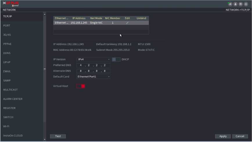
| Net Mode | Multi-address: Two Ethernet ports work separately through either of which you can request the Device to provide the services such as HTTP and RTSP. You need to configure a default Ethernet port (usually the Ethernet port 1 by default) to request the services from the device end such as DHCP, Email and FTP. If one of the two Ethernet ports is disconnected as detected by networking testing, the system network status is regarded as offline.
Fault Tolerance: Two Ethernet ports share one IP address. Normally only one Ethernet port is working and when this port fails, the other port will start working automatically to ensure the network connection. When testing the network status, the network is regarded as offline only when both of the two Ethernet ports are disconnected. The two Ethernet ports are used under the same LAN. Load Balance: Two network cards share one IP address and they are working at the same time to share the network load averagely. If one of them fails, the other can continue working normally. When testing the network status, the network is regarded as offline only when both of the two Ethernet ports are disconnected. The two Ethernet ports are used under the same LAN. |
|||
| The Device with single Ethernet port does not support this | ||||
| function. | ||||
| Default Ethernet
Port |
In the Ethernet Card list, select an Ethernet port as a default port. This setting is available only when the Multi-address is
selected in the Net Mode list |
|||
| IP Version | In the IP Version list, you can select IPv4 or IPv6. Both versions are supported for access. | |||
| MAC Address | Displays the MAC address of the Device. | |||
| DHCP | Enable the DHCP function. The IP address, subnet mask and default gateway are not available for configuration once DHCP is enabled.
If DHCP is effective, the obtained information will display in the IP Address box, Subnet Mask box and Default Gateway box. If not, all values show 0.0.0.0. If you want manually to configure the IP information, disable the DHCP function first. If PPPoE connection is successful, the IP address, subnet mask, default gateway, and DHCP are not available for configuration. |
|||
| IP Address | Enter the IP address and configure the corresponding subnet | |||
| Subnet Mask | . | |||
| Default Gateway | IP address and default gateway must be in the same network | |||
| segment. | ||||
| DNS DHCP | Enable the DHCP function to get the DNS address from router. | |||
| Preferred DNS | In the Preferred DNS box, enter the IP address of DNS. | |||
Parameter
Description
| Alternate DNS | In the Alternate DNS box, enter the IP address of alternate DNS. |
| MTU | In the MTU box, enter a value for network card. The value ranges from 1280 byte through 1500 byte. The default is 1500. The suggested MTU values are as below.
1500: The biggest value of Ethernet information package. This value is typically selected if there is no PPPoE or VPN connection, and it is also the default value of some routers, network adapters and switches. 1492: Optimized value for PPPoE. 1468: Optimized value for DHCP. 1450: Optimized value for VPN. |
| Test | Click Test to test if the entered IP address and gateway are interworking. |
You can configure the maximum connection accessing the Device from Client such as WEB, Platform, and Mobile Phone and configure each port settings.
Step1 Select Main Menu ^ NETWORK ^ PORT. The PORT interface is displayed. See Figure 2.161.
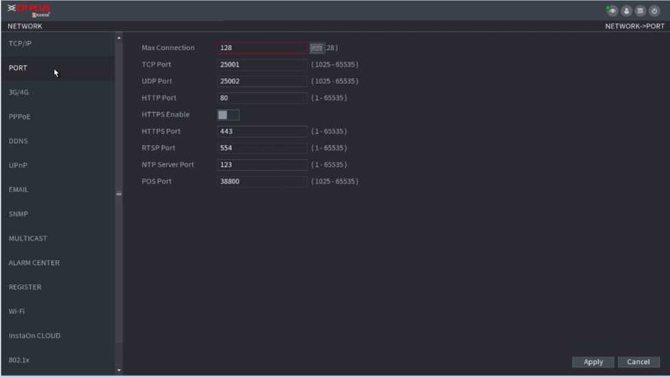
Figure 2.161
Step2 Configure the settings for the connection parameters.
![]()
The connection parameters except Max Connection cannot take effects until the Device has been restarted.
| Parameter | Description |
| Max Connection | The allowable maximum clients accessing the Device at the same time, such as WEB, Platform, and Mobile Phone.
Select a value between 1 and 128. The default value setting is 128. |
| TCP Port | The default value setting is 25001. You can enter the value according to your actual situation. |
| UDP Port | The default value setting is 25002. You can enter the value according to your actual situation. |
| HTTP Port | The default value setting is 80. You can enter the value according to your actual situation.
If you enter other value, for example, 70, and then you should enter 70 after the IP address when logging in the Device by browser. |
| RTSP Port | The default value setting is 554. You can enter the value according to your actual situation. |
| POS Port | Data transmission. The value range is from 1 through 65535.
The default value is 38800. |
| HTTPS Enable | Enable HTTPS. |
| HTTPS Port | HTTPS communication port. The default value setting is 443. You can enter the value according to your actual situation. |
Step4 Click Apply to complete the settings.
PPPoE is another way for the Device to access the network. You can establish network connection by configuring PPPoE settings to give the Device a dynamic IP address in the WAN. To use this function, firstly you need to obtain the username and password from the Internet Service Provider.
Step1 Select Main Menu ^ NETWORK ^ PPPoE. The PPPoE interface is displayed. SFigure 2.162.
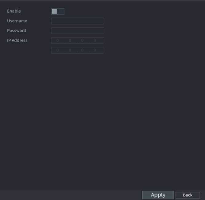
Figure 2.162
Step2 Enable the PPPoE function.
Step3 In the Username box and Password box, enter the username and password accordingly provided by the Internet Service Provider.
Step4 Click Apply to complete the settings.
The system pops up a message to indicate the successfully saved. The IP address appears on the PPPoE interface.
You can use this IP address to access the Device.
When the PPPoE function is enabled, the IP address on the TCP/IP interface cannot be modified.
When the IP address of the Device changes frequently, the DDNS function can dynamically refresh the correspondence between the domain on DNS and the IP address, ensuring you access the Device by using the domain.
Preparations
Ensure the Device supports the DDNS Type and log in the website provided by the DDNS service provider to register the information such as domain from PC located in the WAN.
After you have registered and logged in the DDNS website successfully, you can view the information of all the connected devices under this username.
Stepl Select Main Menu ^ NETWORK ^ DDNS. The DDNS interface is displayed. See Figure 2.163.
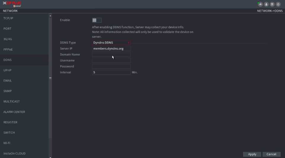
Figure 2.163
Step2 Configure the settings for the DDNS parameters.
| Parameter | Description |
| Enable | Enable the DDNS function.
After enabling DDNS function, the third-party might collect your Device information. |
| DDNS Type | Type and address of DDNS service provider.
Type: Dyndns DDNS; address: members.dyndns.org Type: NO-IP DDNS; address: dynupdate.no-ip.com Type: CN99 DDNS; address: members.3322.org |
| Host IP | |
| Domain Name | The domain name for registering on the website of DDNS service provider. |
| Username | Enter the username and password obtained from DDNS service provider. You need to register (including username and password) on the website of DDNS service provider. |
| Password | |
| Interval | Enter the amount of time that you want to update the DDNS. |
Step2 Configure the settings for the DDNS parameters.
Step3 Click Apply to complete the settings. Enter the domain name in the browser on your PC, and then press Enter.
If the web interface of the Device is displayed, the configuration is successful. If not, the configuration is failed.
You can map the relationship between the LAN and the WAN to access the Device on the LAN through the IP address on the WAN.
Preparations
Login the router to set the WAN port to enable the IP address to connect into the WAN. Enable the UPnP function at the router. Connect the Device with the LAN port on the router to connect into the LAN.
Select Main Menu ^ NETWORK ^ TCP/IP, configure the IP address into the router IP address range, or enable the DHCP function to obtain an IP address automatically.
Step1 Select Main Menu ^ NETWORK ^ UPnP. The UPnP interface is displayed. See Figure 2.164 and Figure 2.165.
Figure 2.164
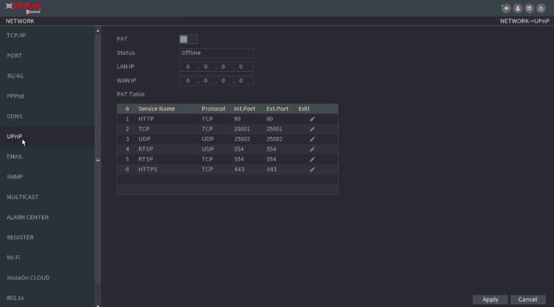
HTTP
TCP
80
80
Service Name
Protocol
Int.Port
OK Cancel
Step2 Configure the settings for the UPnP parameters.
| Parameter | Description | ||||
| PAT | Enable the UPnP function. | ||||
| Status | Indicates the status of UPnP function.
Offline: Failed. Online: Succeeded. |
||||
| LAN IP | Enter IP address of router on the LAN. | ||||
| After | mapping succeeded, the system obtains IP address | ||||
| automatically without performing any configurations. | |||||
| WAN IP | Enter IP address of router on the WAN | . | |||
| After | mapping succeeded, the system obtains IP address | ||||
| automatically without performing any configurations. | |||||
| The settings in PAT table correspond to the UPnP PAT table on the router.
Service Name: Name of network server. Protocol: Type of protocol. Int. Port: Internal port that is mapped on the Device. Ext. Port: External port that is mapped on the router. |
|||||
| PAT Table | To avoid the conflict, when setting the external port, try to use the ports from 1024 through 5000 and avoid popular ports from 1 through 255 and system ports from 256 through 1023. When there are several devices in the LAN, properly arrange the ports mapping to avoid mapping to the same external | ||||
| port. | |||||
| When establishing a mapping relationship, ensure the mapping ports are not occupied or limited. The internal and external ports of TCP and UDP must be the same and cannot be | |||||
| modified. | |||||
| Click | □ | to modify the external port | . | ||
Step3 Click Apply to complete the settings. In the browser, enter http://WAN IP: External IP port. You can visit the LAN Device.
You can configure the email settings to enable the system to send the email as a notification when there is an alarm event occurs.
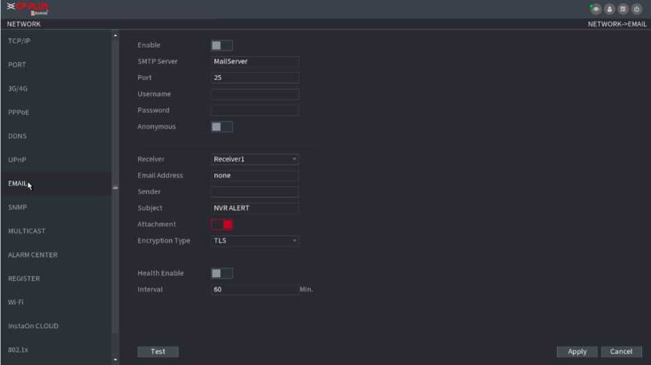
Step1 Select Main Menu ^ NETWORK ^ EMAIL. The EMAIL interface is displayed. See Figure 2.166.
Figure 2.166
Step2 Configure the settings for the email parameters.
| Parameter | Description |
| Enable | Enable the email function. |
| SMTP Server | Enter the address of SMTP server of sender’s email account. |
| Port | Enter the port value of SMTP server. The default value setting is 25. You can enter the value according to your actual situation. |
| Username
Password |
Enter the username and password of sender’s email account. |
| Anonymity | If enable the anonymity function, you can login as anonymity. |
| Mail Receiver | In the Mail Receiver list, select the number of receivers that you want to receive the notification. The Device supports up to three mail receivers. |
| Email Address | Enter the email address of mail receiver(s). |
| Sender | Enter the sender’s email address. It supports maximum
three |
| Title | Enter the email subject. Supports English and Arabic numerals. It supports maximum 64 characters. |
| Attachment | Enable the attachment function. When there is an alarm event, the system can attach snapshots as an attachment to |
| Authentication | -^-7 : —
Select the encryption type: NONE, SSL, or TLS. For SMTP server, the default encryption type is TLS. |
| Interval (Sec.) | This is the interval that the system sends an email for the same type of alarm event, which means, the system does not send an email upon any alarm event.
This setting helps to avoid the large amount of emails caused by frequent alarm events. The value ranges from 0 to 3600. 0 means that there is no interval. |
| Health Enable | Enable the health test function. The system can send a test email to check the connection. |
| Interval (Min.) | This is the interval that the system sends a health test |
| Test | Click Test to test the email sending function. If the configuration is correct, the receiver’s email account will receive the email.
Before testing, click Apply to save the settings. |
Step 3 Click Apply to complete the settings.
![]()
You can connect the Device with some software such as MIB Builder and MG-SOFT MIB Browser to manage and control the Device from the software.
Preparations
Install the software that can manage and control the SNMP, such as MIB Builder and MG-SOFT MIB Browser Obtain the MIB files that correspond to the current version from the technical support.
Stepl Select Main Menu ^ NETWORK ^ SNMP. The SNMP interface is displayed. See Figure 2.167.
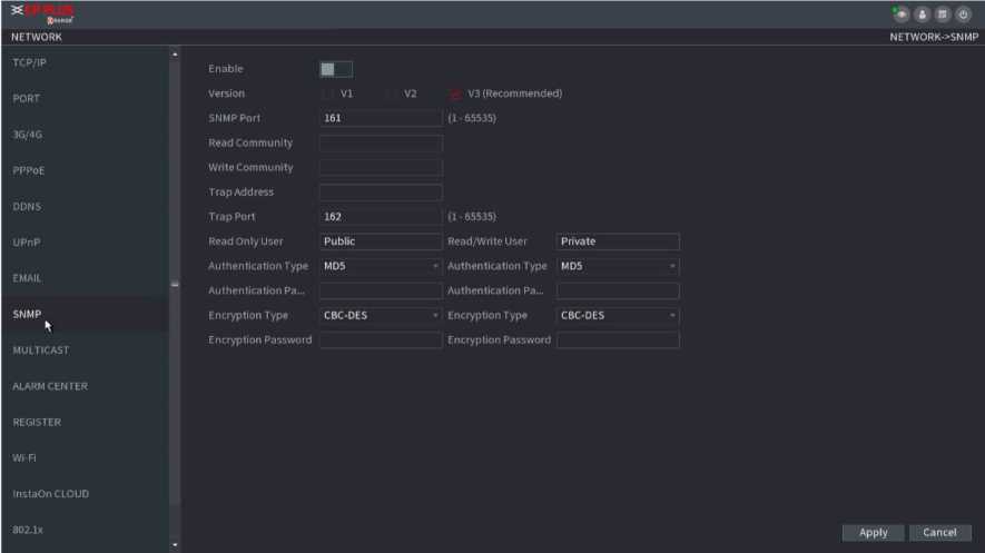
Figure 2.167
Step2 Configure the settings for the SNMP parameters.
| Parameter | Description |
| Enable | Enable the SNMP function. |
| Version | Select the check box of SNMP version(s) that you are using.
The default version is V3. There is a risk of select V1 or V2. |
| SNMP Port | Indicates the monitoring port on the agent program. |
| Read Community | Indicates the read/write strings supported by the agent program. |
| Write Community | |
| Trap Address | Indicates the destination address for the agent program to send the Trap information. |
| Trap Port | Indicates the destination port for the agent program to send the Trap information. |
| Read Only User | Enter the username that is allowed to access the Device and has the “Read Only” permission. |
| Read/Write User | Enter the username that is allowed to access the Device and has the “Read and Write” permission. |
| Authentication Type | Includes MD5 and SHA. The system recognizes automatically. |
| Authentication Password | Enter the password for authentication type and encryption type. The password should be no less than eight characters. |
| Encryption Password | |
| Encryption Type | In the Encryption Type list, select an encryption type. The default setting is CBC-DES. |
Step3 Compile the two MIB files by MIB Builder.
Step4 Run MG-SOFT MIB Browser to load in the module from compilation.
Step5 On the MG-SOFT MIB Browser, enter the Device IP that you want to manage, and then select the version number to query.
Step6 On the MG-SOFT MIB Browser, unfold the tree-structured directory to obtain the configurations of the Device, such as the channels quantity and software version.
When you access the Device from the network to view the video, if the access is exceeded, the video will not display. You can use the multicast function to group the IP to solve the problem.
Step1 Select Main Menu ^ NETWORK ^ MULTICAST. The MULTICAST interface is displayed. See Figure 2.168.
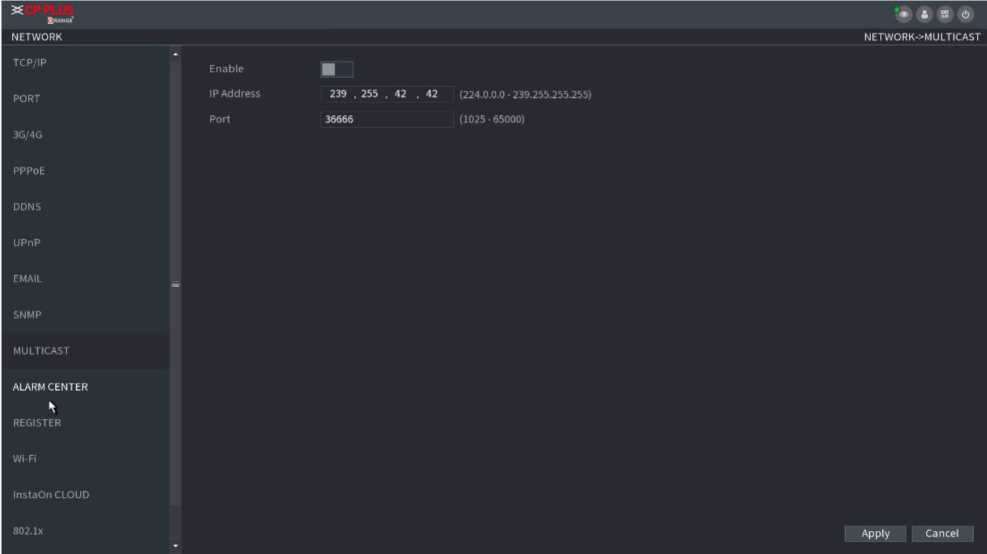
Figure 2.168
Step2 Configure the settings for the multicast parameters.
| Parameter | Description |
| Enable | Enable the multicast function. |
| IP Address | Enter the IP address that you want to use as the multicast IP.
The IP address ranges from 224.0.0.0 through 239.255.255.255. |
| Port | Enter the port for the multicast. The port ranges from 1025 through 65000. |
Step3 Click Apply to complete the settings. You can use the multicast IP address to login the web.
On the web login dialog box, in the Type list, select MULTICAST. The web will automatically obtain the multicast IP address and join. Then you can view the video through multicast function.
You can configure the alarm center server to receive the uploaded alarm information. To use this function, the Alarm Upload check box must be selected.
Step1 Select Main Menu ^ NETWORK ^ ALARM CENTER. The ALARM CENTER interface is displayed. See Figure 2.169.
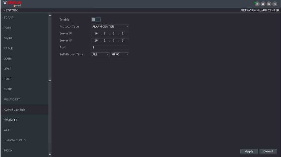
Figure 2.169
Step2 Configure the settings for the alarm center parameters.
| Parameter | Description |
| Enable | Enable the alarm center function. |
| Protocol Type | In Protocol Type list, select protocol type. The default is ALARM CENTER. |
| Host IP
Port |
The IP address and communication port of the PC installed with alarm client. |
| Self-Report Time | In the Self-Report Time list, select time cycle and specific time for uploading alarm. |
Step3 Click Apply to complete the settings.
You can register the Device into the specified proxy server which acts as the transit to make it easier for the client software to access the Device.
Step1 Select Main Menu ^ NETWORK ^ REGISTER. The REGISTER interface is displayed. See Figure 2.170.
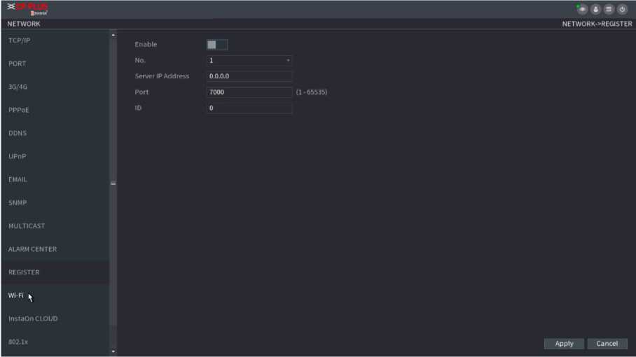
Figure 2.170
Step2 Configure the settings for the register parameters.
| Function | Description |
| Enable | Enable the register function. |
| Server IP Address | Enter the server IP address or the server domain that you want to register to. |

![]()

![]()

| Port | Enter the port of the server. |
|---|---|
| Sub Service ID | This ID is allocated by the server and used for the Device. |
Step 3 Click Apply to complete the settings.
INSTAON is a kind of convenient private network penetration technology. You do not need to apply for dynamic domain name, doing port mapping or deploying transit server. You can add NVR devices through the below way to achieve the purpose of managing multiple NVR devices at the same time.
Scan the QR code, download mobile app, and then register an account. For details, see Mobile App Operation.
Connect the NVR device to the Internet, otherwise INSTAON cannot run
properly.
Step1 Select Main Menu ^ NETWORK ^ INSTAON. The INSTAON interface is displayed. See Figure 2.171.
NETWORK-XnstaOn CLOUD
NETWORK
TCP/IP
PORT
3G/4G
PPPOE
DDNS
UPnP
SNMP
MULTICAST
ALARM CENTER
REGISTER
Wi-Fi
InstaOrjCLOUD
Enable
InstaOn Cloud allows you to access your device remotely in a secure way. Activating InstaOn will synchronize all your device information, e.g.
Device Model Code; Device Serial Number; Mac Address; and IP address to the InstaOn server.
Note: All information collected will only be used to make your device accessible remotely via WAN.
Status
Step2 Enable the INSTAON function.
Offline
InstaOn Cloud ID
Apply Cancel
Figure 2.171
After the INSTAON function is enabled and connected to the Internet, the system will collects your information for remote access, and the information includes but not limited to email address, MAC address, and device serial number.
You can start adding the device –
Cell Phone Client: Use your mobile phone to scan the QR code to add the device into the Cell Phone Client, and then you can start accessing the Device.
![]() Platform: Obtain the Device SN by scanning the QR code. Go to the INSTAON management platform and add the Device SN into the platform. Then you can access and manage the device in the WAN. For details, refer to the INSTAON operation manual.
Platform: Obtain the Device SN by scanning the QR code. Go to the INSTAON management platform and add the Device SN into the platform. Then you can access and manage the device in the WAN. For details, refer to the INSTAON operation manual.
on the top right of the interfaces
You can also enter the QR code of Cell Phone Client and Device SN by clicking after you have entered the Main Menu. To use this function, take adding device into Cell Phone Client as an example.
The following contents are introduced in the example of mobile App.
Step1 Scan the QR code to download and install the mobile App.
Step2 Select Camera and enter the main interface.
Step3 Register device in the mobile App:
![]()
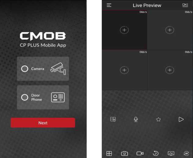
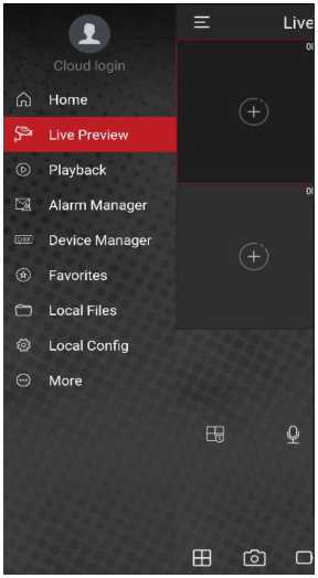
a.
Click
and select Device Manager. See Figure 2.172.
Figure 2.172
- Click and enter the Add Device interface.
- Mobile App supports device initialization.
- Select Wired Device > INSTAON to enter the INSTAON interface.
- Click the QR code icon behind the SN to enter the QR code scan interface.
- Scan the device label or scan the SN QR code got by selecting Main Menu ^ Network ^ INSTAON. When the scan is successful, the device SN will be displayed in the SN item.
- Enter username and password.
Step4 After device registration on mobile App, click Start Preview and you can see the monitor screen.
Device needs to pass 802.1x certification to enter the LAN.
Step1 Select Main Menu ^ NETWORK ^ 802.1x.
The 802.1x interface is displayed. See Figure 2.173 and Figure 2.174.
Ethernet Card Ethernetl
Enable □
Authentication PEAP
CA Certificate
Browse
Username
Password
Apply Back
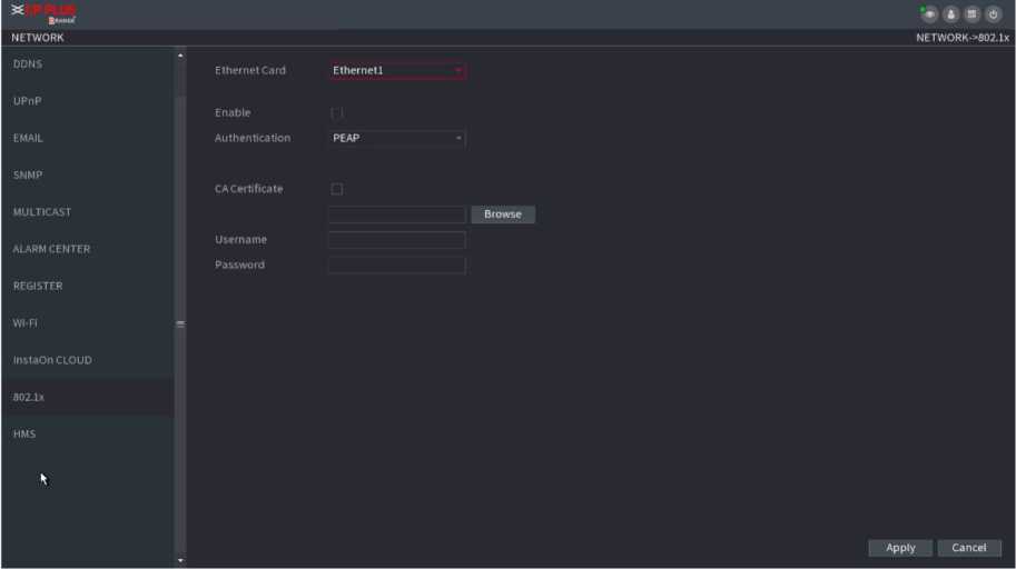
Figure 2.174
Step2 Select the Ethernet card you want to certify.
Step3 Select Enable and configure parameters.
| Parameter | Description |
| Authentication | PEAP: Protected EAP protocol.
TLS: Transport Layer Security. Provide privacy and data integrity between two communications application programs. |
| Identity | It can be configured when Authentication is TLS. |
| CA Certificate | Enable it and click Browse to import CA certificate from flash drive. |
| Username | The username shall be authorized at server. |
| Password | Password of the corresponding username. |
| Client Certificate
Private Key |
When Authentication is TLS, click Browse to import from flash drive. |
| Private Key Password | It can be configured when Authentication is TLS. |
Step 4 Click Apply to complete the settings.
You can manage the storage resources (such as record file) and storage space. So that it is easy for you to use and enhance storage space usage.
You can set basic storage parameters.
Stepi Select Main Menu ^ STORAGE ^ BASIC. The Basic interface is displayed. See Figure 2.175.
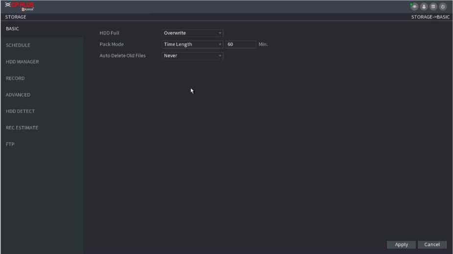
Figure 2.175
| Parameter | Description |
| HDD Full | Configure the settings for the situation all the read/write discs are full, and there is no freer disc.
Select Stop Record to stop recording Select Overwrite to overwrite the recorded video files always from the earliest time. |
| Pack Mode | Configure the time length and file length for each |
| Auto-Delete Old Files | Configure whether to delete the old files and if yes, configure the days. |
| The auto delete file cannot be recovered! |
Step3 Click Apply or Save to complete setup.
You can set schedule record and schedule snapshot. NVR can record or snapshot as you specified.
You can view and sett HDD properties and format HDD. You can view current HDD type, status, capacity and etc. The operation includes format HDD, and change HDD property (read and write/read-only/redundancy).
- To prevent files be overwritten in the future, you can set HDD as read-only.
- To backup recorded video file, you can set HDD as redundant HDD.
Step1 Select Main Menu ■> Storage ■> HDD MANAGER, The HDD MANAGER interface is displayed. See Figure 2.176.
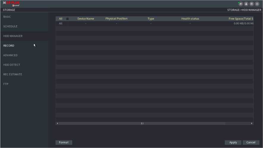
Figure 2.176
Step2 Select HDD and then select a time from the dropdown list.
Step3 Click Apply button to complete the setup. System needs to restart to activate current setup if you want to format the HDD.
After you set schedule record or schedule snapshot function, set auto record/snapshot function so that the NVR can automatically record or snapshot.
This function is for some series product only.
The HDD detect function is to detect HDD current status so that you can clearly understand the HDD performance and replace the malfunction HDD.
There are two detect types:
- Quick detect is to detect via the universal system files. System can quickly complete the HDD scan. If you want to use this function, make sure the HDD is in use now. If the HDD is removed from other device, make sure the HDD once storage the record files when installed on current device.
- Global detect adopts Windows mode to scan. It may take a long time and may affect the HDD that is recording.
Step1 Select Main Menu ^ STORAGE ^ HDD DETECT ^ Manual Detect. The Manual Detect interface is displayed. See Figure 2.177.
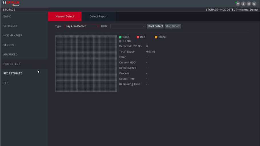
Figure 2.177
Step2 In the Type list, select Key Area Detect or Global Detect; and in the HDD list, select the HDD that you want to detect.
Step3 Click Start Detect.
The system starts detecting the HDD and displays the detection information.
When system is detecting HDD, click Stop Detect to stop current detection. Click Start Detect to detect again.
After the detect operation, you can go to the detect report to view corresponding information. Replace the malfunction HDD in case there is data loss.
Step1 Select Main Menu ^ STORAGE ^ HDD DETECT ^ Detect Report. The Detect Report interface is displayed. See Figure 2.178.
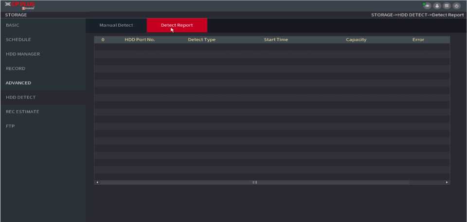
Figure 2.178
Step2 Click , The Details interface is displayed. You can view detecting results and S.M.A.R.T reports.
Record estimate function can calculate how long you can record video according to the HDD capacity, and calculate the required HDD capacity according to the record period.
Step1 Select Main Menu ■> STORAGE ■> REC ESTIMATE. The REC ESTIMATE interface is displayed. See Figure 2.179.
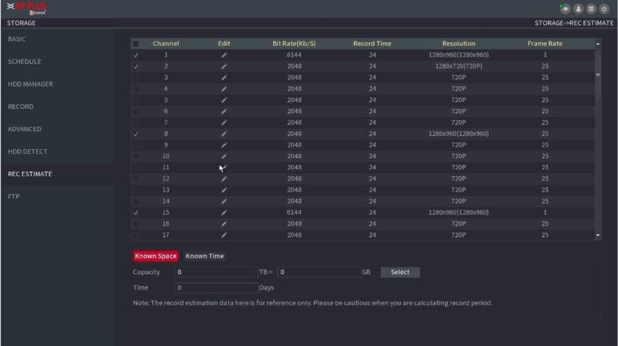
![]()
Figure 2.179
The Edit dialogue box is displayed. See Figure 2.180. You can configure the Resolution, Frame Rate, Bit Rate and Record Time for the selected channel.
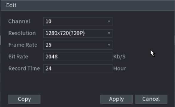
Figure 2.180
Step3 Click Apply to save the settings.
Then the system will calculate the time period that can be used for storage according to the channels settings and HDD capacity.
Click Copy to copy the settings to other channels.
Ca lculating Recordi ng Time
Stepl On the REC ESTIMATE interface, click the Known Space tab. The Known Space interface is displayed. See Figure 2.181.

Figure 2.181
Step2 Click Select. The Select HDD(s) interface is displayed.
Step 3 Select the check box of the HDD that you want to calculate. In the Known Space tab, in the Time box, the recording time is displayed. See Figure 2.182.
Known Space Known Time
Time 0 Days
capacity o tb= □ gb
Note: The record estimation data here is for reference only. Please be cautious when you are calculating record period.
Figure 2.182
Stepl On the REC ESTIMATE interface, click the Known Time tab. The Known Time interface is displayed. See Figure 2.183.
Known Space Known Time
Time 0 Days
Capacity 0 TB – U GB
Note: The record estimation data here is for reference only. Please be cautious when you are calculating record period.
Figure 2.183
Step 2 In the Time box, enter the time period that you want to record. In the Capacity box, the required HDD capacity is displayed.
You can store and view the recorded videos and snapshots on the FTP server.
Preparations
Purchase or download FTP (File Transfer Protocol) server and install it on your PC.
![]()
For the created FTP user, you need to set the write permission; otherwise the upload of recorded videos and snapshots will be failed.
Step1 Select Main Menu ^ STORAGE ^ FTP. The FTP interface is displayed. See Figure 2.184.
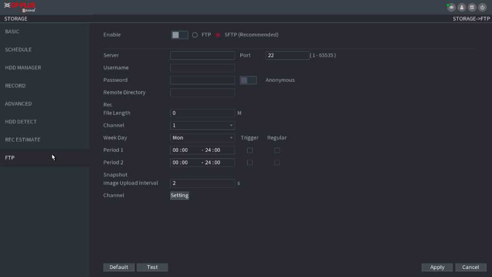
Figure 2.184
Step2 Configure the settings for the FTP settings parameters.
| Parameter | Description |
| Enable | Enable the FTP upload function. |
| FTP type | Select FTP type.
FTP: Plaintext transmission. SFTP: Encrypted transmission (recommended) |
| Server | IP address of FTP server. |
| Port | FTP: The default is 21.
SFTP: The default is 22. |
| Anonymity | Enter the username and password to login the FTP server. Enable the anonymity function, and then you can
login anonymously without entering the username and password. |
| Username | |
| Password | |
| Remote Directory | Create folder on FTP server.
If you do not enter the name of remote directory, system automatically creates the folders according to the IP and time. If you enter the name of remote directory, the system creates the folder with the entered name under the FTP root directory first, and then automatically creates the folders according to the IP and time. |
| File Length(M) | Enter the length of the uploaded recorded video.
If the entered length is less than the recorded video length, only a section of the recorded video can be uploaded. If the entered length is more than the recorded video length, the whole recorded video can be uploaded. If the entered length is 0, the whole recorded video will be uploaded. |
| Image Upload Interval (Sec.) | If this interval is longer than snapshot interval, the system takes the recent snapshot to upload. For example, the interval is 5 seconds, and snapshot interval is 2 seconds per snapshot, the system uploads the recent snapshot every 5 seconds.
If this interval is shorter than snapshot interval, the system uploads the snapshot per the snapshot interval. For example, the interval is 5 seconds, and snapshot interval is 10 seconds per snapshot, the system uploads the snapshot every 10 seconds. To configure the snapshot interval, select Main Menu ^ CAMERA ■> ENCODE ^ Snapshot. |
| Channel | Select the channel that you want to apply the FTP settings. |
| Weekday | Select the weekday and set the time period that you want to upload the recorded files. You can set two periods for each weekday. |
| Record type | Select the record type (Alarm, Intel, MD, and General) that you want to upload. The selected record type will be uploaded during the configured time period. |
Step3 Click Test.
The system pops up a message to indicate success or failure. If failed, check the network connection or configurations.
Step4 Click Apply to complete the settings.
You can set device general information. It includes device information, system date.
After setting RS-232 parameters, the NVR can use the COM port to connect to other device to debug and operate.
Step1 Select MAIN MENU ^ SYSTEM ^RS232. The RS232 interface is displayed. See Figure 2.185.
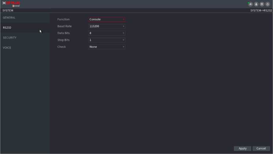
Figure 2.185
| Parameter | Description |
| Function | Select serial port control protocol.
Console: Upgrade the program and debug with the console and mini terminal software. Keyboard: Control this Device with special keyboard. Adapter: Connect with PC directly for transparent transmission of data. Protocol COM: Configure the function to protocol COM, in order to overlay card number. PTZ Matrix: Connect matrix control. |
| Different series products support different RS232 | |
| functions. The actual product shall prevail. | |
| Baud Rate | Select Baud rate, which is 115200 by default. |
| Data Bits | It ranges from 5 to 8, which is 8 by default. |
| Stop Bits | It includes 1 and 2. |
| Parity | It includes none, odd, even, mark and null. |
Step3 Click Apply.
You can set security options to strengthen device security and use the device in a much safer way. See in Figure 2.186.
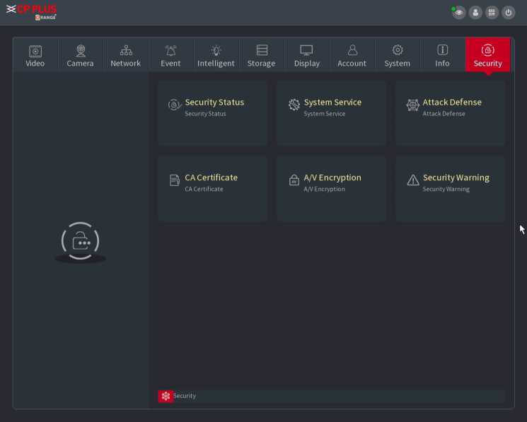
Figure 2.186
Security scanning helps get a whole picture of device security status. You can scan user, service and security module status for detailed information about the security status of the device.
• Detecting User and Service
Green icon represents a healthy status of the scanned item, and orange icon represents a risky status.
Login authentication: When there’s a risk in the device configuration, the icon will be in orange to warn risk. You can click Details to see the detailed risk description.
User Status: When one of device users or ONViF users uses weak password, the icon will be in orange to warn risk.
You can click Details to optimize or ignore the risk warning.
Figure 2.187
• Configuration Security: When there’s a risk in the device configuration, the icon will be in orange to warn risk. You can click Details to see the detailed risk description. See Figure 2.188 and Figure 2.189.
Figure 2.188
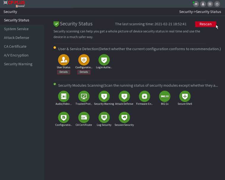
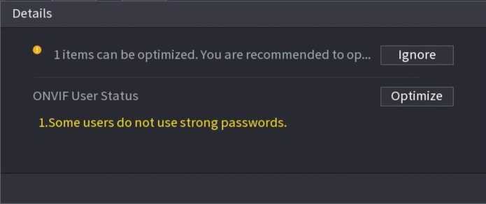
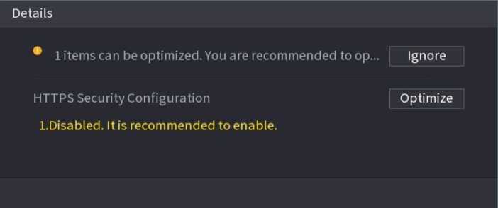
Scanning Security Modules
This area shows the running status of security modules. For details about the security modules, move mouse pointer on the icon to see the on-screen instructions.
• Scanning Security Status
You can click Rescan to scan security status.
You can set NVR basic information such as basic services, 802.1x and HTTPS.
Step 1 Select Main Menu ^ SECURITY ^ System Service ^ BasicServices.
The Basic Services interface is displayed. See Figure 2.190.
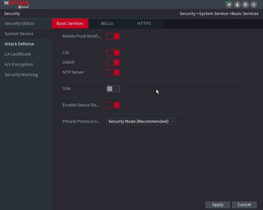
Figure 2.190
Step 2 Select Basic Services and configure parameters.
There might be safety risk when Mobile Push Notifications, CGI, ONVIF, SSH and NTP Server is enabled.
| Parameter | Description |
| Mobile Push Notifications | After enabling this function, the alarm triggered by the NVR can be pushed to a mobile phone. This function is enabled by default. |
| CGI | If this function is enabled, the remote devices can be added through the CGI protocol. This function is enabled by default. |
| ONVIF | If this function is enabled, the remote devices can be added through the ONVIF protocol. This function is enabled by default. |
| NTP Server | After enabling this function, a NTP server can be used to synchronize the device. This function is enabled by default. |
| SSH | After enabling this function, you can use SSH service. This function is disabled by default. |
| Enable Device Discovery | After enabling this function, the NVR can be found by other devices trough searching. |
| Private Protocol Authentication Mode |
authentication when connecting to NVR.
does not support Digest access authentication. |
Step 3 Click Apply to complete the settings.
The device needs to pass 802.1x certification to enter the LAN.
Step 1 Select Main Menu ^ SECURITY ^ System Service ^ 802.1x.
The 802.1x interface is displayed. See Figure 2.191.

Figure 2.191
Step 2 Select the Ethernet card you want to certify.
Step 3 Select Enable and configure parameters.
| Parameter | Description |
| Authentication |
application programs. |
| CA Certificate | Enable it and click Browse to import CA certificate from flash drive. For details about importing and creating a certificate. |
| Username | The username shall be authorized at server. |
| Password | Password of the corresponding username. |
Step 4 Click Apply to complete the settings.
We recommend that you enable HTTPS function to enhance system security.
Step 1 Select Main Menu ■> SECURITY ^ System Service ^ HTTPS.
The HTTPS interface is displayed. See Figure 2.192.
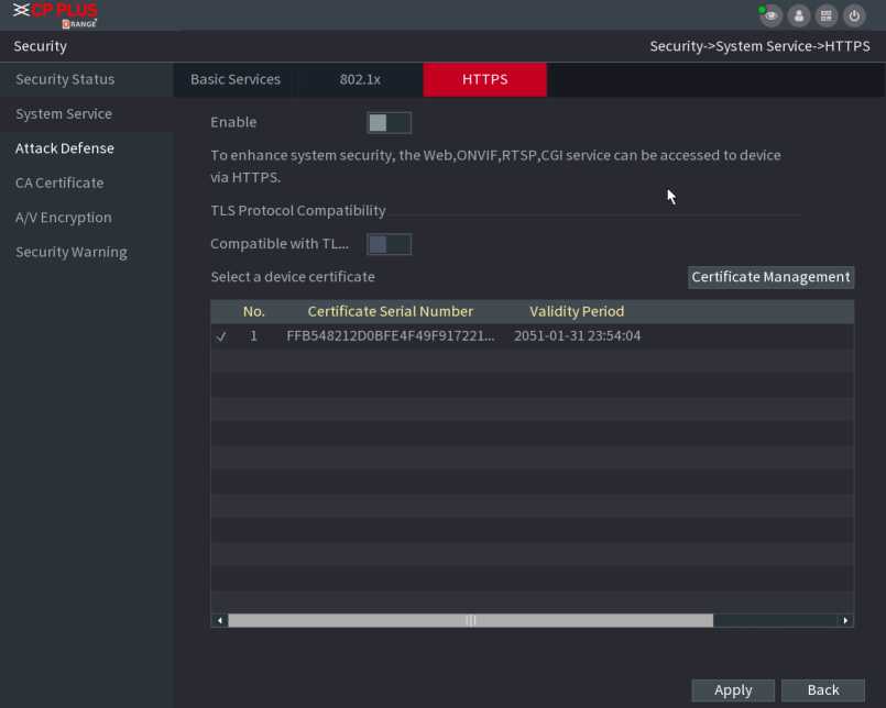
Figure 2.192
Step 3 (Optional) Enable Compatible with TLSv1.1 and earlier versions to allow protocol compatibility.
Step 4 Click Certificate Management to create or import a HTTPS certificate from USB drive. For details about importing or creating a CA certificate, see “4.14.4 CA Certificate”.
Step 5 Select a HTTPS certificate.
Step 6 Click Apply to complete the settings.
Step 1 Select Main Menu ■> SECURITY ^ Attack Defense ■> Firewall.
The HTTPS interface is displayed. See Figure 2.193.
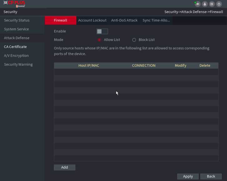
Figure 2.193
Step 2 Select Enable to enable firewall.
Step 3 Configure the parameters.
| Parameter | Description | |
| Mode | Mode can be configured when Type is Network Access.
successfully with IP/MAC hosts in Trusted Sites.
IP/MAC hosts in Blocked Sites. |
|
| Add | When Type is Network Access, you can configure IP Address, IP Segment and MAC Address. | |
| Type | You can select IP address, IP segment and MAC address. | |
| IP Address | Enter IP Address, Start Port and End Port that is allowed or | |
| Start Port | forbidden. | |
| End Port | When Type is IP Address, they can be configured. Start Port and End Port can be configured only in Network Access Type. | |
| Start Address | Enter Start Address and End Address of IP Segment. | |
| When Type is IP Segment, they can be configured. | ||
| MAC Address | Enter MAC Address that is allowed or forbidden | |
| When Type is MAC Address, they can be configured. | ||
Step 4 Click Apply to complete the settings.
Step 1 Select Main Menu ^ SECURITY ^ Attack Defense ^ Account Lockout
The Account Lockout interface is displayed. See Figure 2.194.
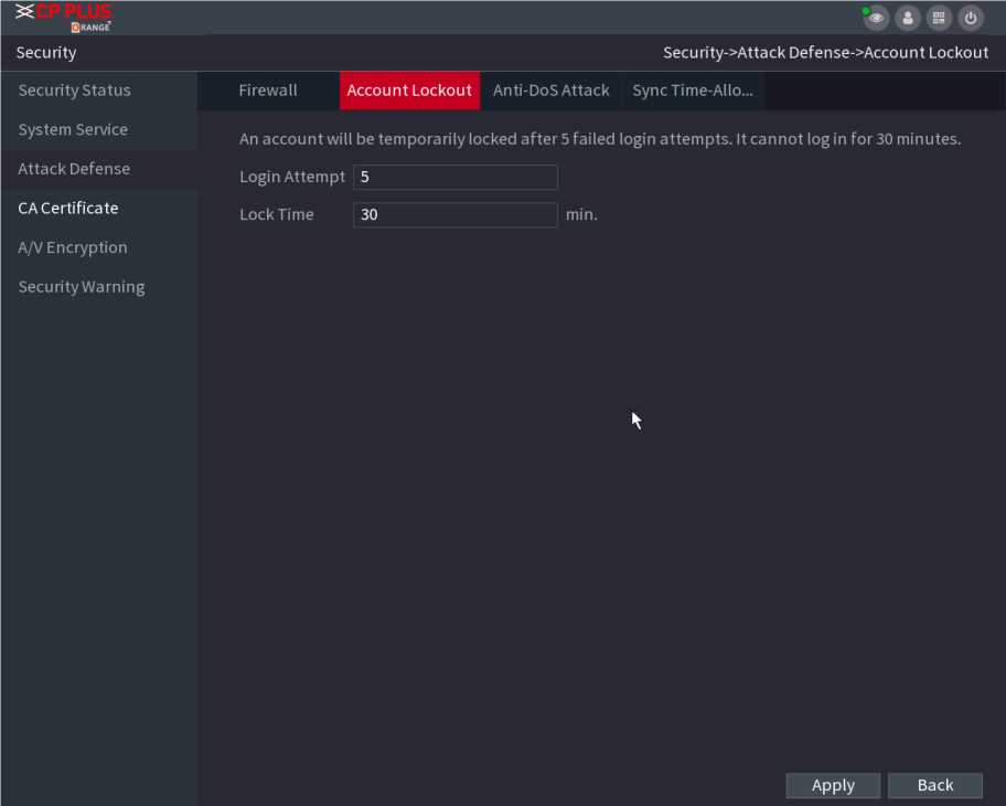
Figure 2.194
| Parameter | Description |
| Attempt(s) | Set the maximum number of allowable wrong password entries. The account will be locked after your entries exceed the maximum number.
Value range: 5 – 30. Default value: 5. |
| Lock Time | Set how long the account is locked for. Value range: 5 -120 minutes.
Default value: 30 minutes. |
Step 3 Click Apply to complete the settings.
You can enable SYN Flood Attack Defense and ICMP Flood Attack Defense to defend the device against Dos attack. See Figure 2.195.
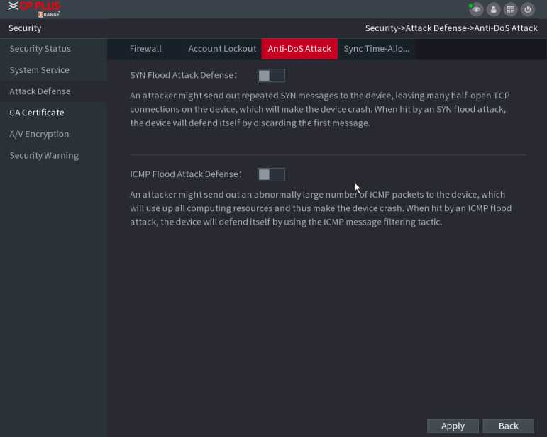
Figure 2.195
The synchronization is only allowed with hosts in the trusted list.
Step 1 Select Main Menu ^ SECURITY ^ Attack Defense ^ SyncTime-Allowlist.
The Sync Time-Whitelist interface is displayed. See Figure 2.196.
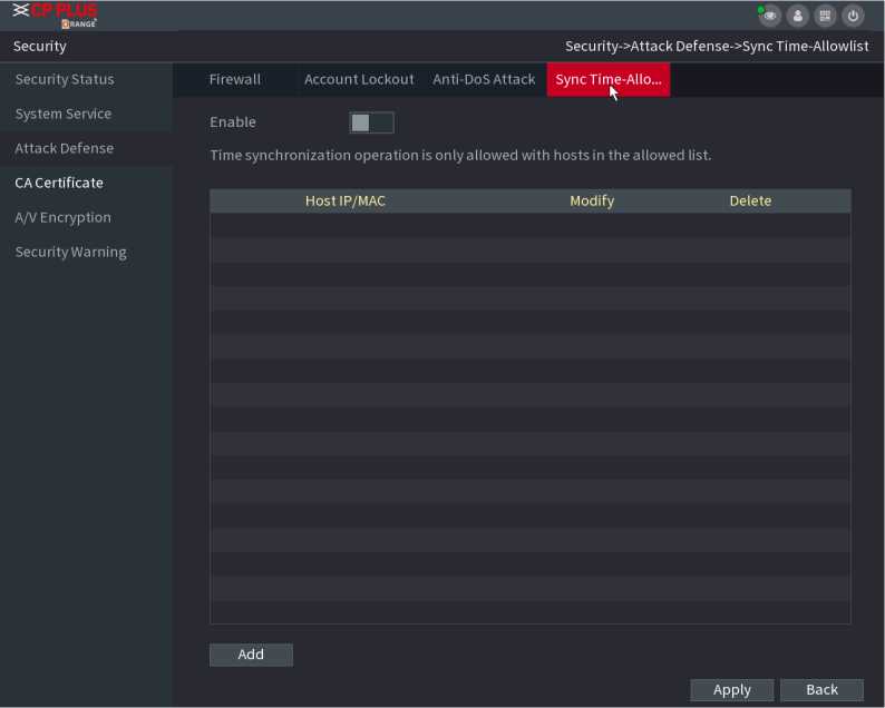
Figure 2.196
Step 2 Select Enable to enable Sync Time-Allowlist function.
Step 3 Configure the parameters.
| Parameter | Description |
| Add | You can add trusted hosts for time synchronization. |
| Type | Select IP address or IP segment for hosts to be added. |
| IP Address | Input the IP address of a trusted host. |
| When Type is IP Address, it can be configured | |
| Start Address | Input the start IP address of trusted hosts. |
| When Type is IP Segment, it can be configured | |
| End Address | Input the end IP address of trusted hosts. |
| When Type is IP Segment, it can be configured |
Step 4 Click Apply to complete the settings.
> Create Certificate
Step 1 Select Main Menu ^ SECURITY ^ CA Certificate ^ Device Certificate.
The Device Certificate interface is displayed. See Figure 2.197.
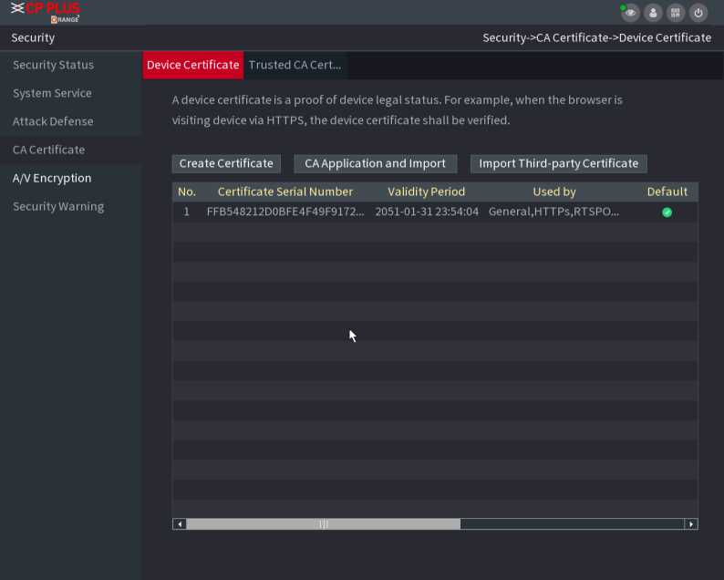
Figure 2.197
| Parameter | Description |
| County | This parameter is user defined. |
| State | This parameter is user defined. |
| City Name | This parameter is user defined. |
| Valid Period | Input a valid period for the certificate. |
| Organization | This parameter is user defined. |
| Organization Unit | This parameter is user defined. |
| Domain Name | Input the domain name or IP address of the certificate. |
Step 3 Click on Create
Step 1 Select Main Menu ^ SECURITY ^ CA Certificate ^ Trusted CA Certificate.
Step 2 Click Install Trusted Certificate.
The Create Certificate is displayed. See Figure 2.198.
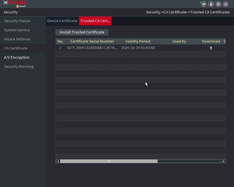
Figure 2.198
Step 3 Click Browse to select the certificate that you want toinstall.
Step 4 Click Import.
The device supports audio and video encryption during data transmission.
Step 1 Select Main Menu ^ SECURITY ^ AUDIO/VIDEO ENCRYPTION ^ Audio/Video Transmission.
The Audio/Video Transmission interface is displayed. See Figure 2.199.
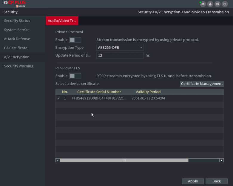
Figure 2.199
| Area | Parameter | Description | |||
| Private
Protocol |
Enable | Enables stream frame encryption by using private protocol. | |||
| eq | There m disabled. | ght be safety risk if this service is | |||
| Encryption Type | Use the default setting. | ||||
| Update Period
of Secret Key |
Secret key update period.
Value range: 0 – 720 hours. 0 means never update the secret key. Default value: 12. |
||||
| RTSP over
TLS |
Enable | Enables RTSP stream encryption by using TLS. | |||
| EQ | There mi disabled. | ght be safety risk if this service is | |||
| Select a device certificate | Select a device certificate for RTSP over TLS. | ||||
| Certificate
Management |
For details about certificate management. | ||||
Step 3 Click Apply to complete the settings.
Step 1 Select Main Menu ^ SECURITY ^ Security Warning ^ SecurityException.
The Security Exception interface is displayed. See Figure 2.200.
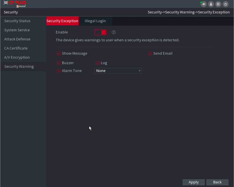
Figure 2.200
Step 2 Select Enable and configure parameters.
| Parameter | Description |
| Alarm-out Port | The alarm device (such as lights, sirens, etc.) is connected to the alarm output port. When an alarm occurs, the NVR device transmits the alarm information to the alarm device. |
| Post-Alarm | When the alarm ends, the alarm extended for a period of time. The time range is from 0 seconds to 300 seconds. |
| Show Message | Check box to enable a pop-up message in your local host PC. |
| Buzzer | Select the check box to activate the buzzer when an alarm occurs. |
| Alarm Tone | Check the box and then select the corresponding audio file from the dropdown list. System plays the audio file when the alarm occurs. |
| Log | Select the check box, the NVR device records the alarm information in the log when an alarm occurs. |
| Send Email | Select the check box. When an alarm occurs, the NVR device sends an email to the set mailbox to notify the user. |
| You need to set the email first. | |
| © | Security Event monitoring explanation. It indicates the type of attacks that can trigger security exception.
|
Step 3 Click Apply to complete the settings.
Step 1 Select Main Menu ■> SECURITY ^ Security Warning ^ IllegalLogin.
The Illegal Login interface is displayed. See Figure 2.201.
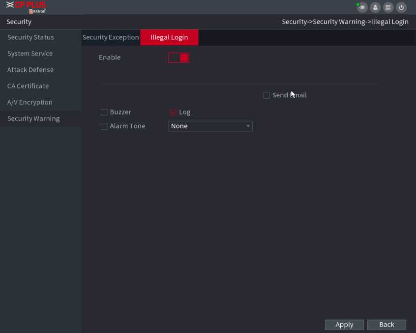
Figure 2.201
Step 2 Select Enable and configure parameters.
| Parameter | Description |
| Alarm-out Port | The alarm device (such as lights, sirens, etc.) is connected to the alarm output port. When an alarm occurs, the NVR device transmits the alarm information to the alarm device. |
| Post Alarm | When the alarm ends, the alarm extended for a period of time. The time range is from 0 seconds to 300 seconds. |
| Buzzer | Select the check box to activate the buzzer when an alarm occurs. |
| Alarm Tone | Check the box and then select the corresponding audio file from the dropdown list. System plays the audio file when the alarm occurs. |
| Log | Select the check box, the NVR device records the alarm information in the log when an alarm occurs. |
| Send Email | Select the check box. When an alarm occurs, the NVR device sends an email to the set mailbox to notify the user. |
You can manage users, user group and ONVIF user, set admin security questions.
- For the username, the string max length is 31-byte, and for the user group, the string max length is 15-byte. The username can only contain English letters, numbers and “_”, “@”, “.”.
- The default user amount is 64 and the default group amount is 20. System account adopts two-level management: group and user. The user authorities shall be smaller than group authorities (The admin user authorities are set by default).
- For group or user management, there are two levels: admin and user. The username shall be unique, and one user shall only belong to one group.
Stepl Select Main Menu ^ ACCOUNT ^ User. The User interface is displayed. See Figure 2.202.
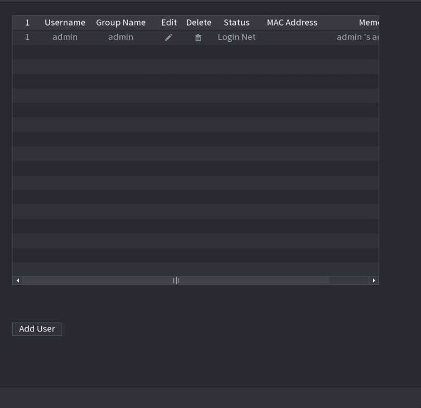
Step2 Click Add User button in Figure 2.202. The Add User interface is displayed. See Figure 2.203.
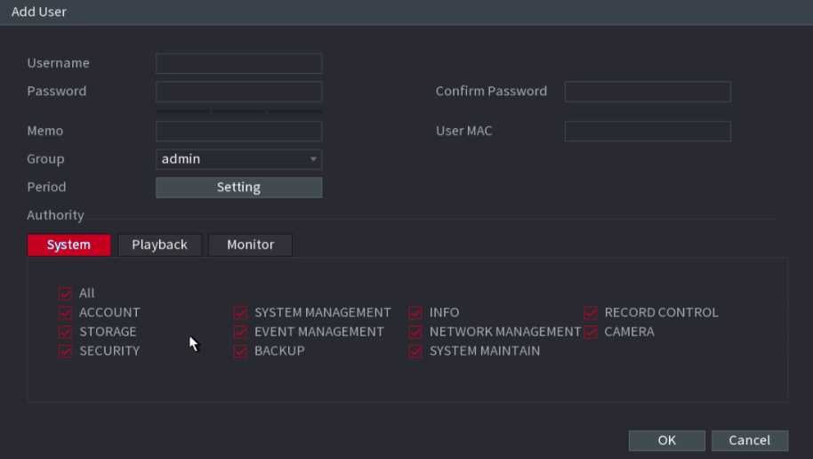
Figure 2.203
Step3 Input the username, password, select the group it belongs to from the dropdown list. Then you can check the corresponding rights for current user.
| Parameter | Description |
| Username | Enter a username and password for the account. |
| Password | |
| Confirm Password | Re-enter the password. |
| Memo | Optional. Enter a description of the account. |
| User MAC | Enter user MAC address |
| Group | Select a group for the account.
The user rights must be within the group permission. |
| Period | Click Set to display Set interface.
Define a period during which the new account can login the device. The new account cannot login the device during the time beyond the set period. |
| Authority | In the Authority area, select the check boxes in the System tab, Playback tab, and Monitor tab.
To manage the user account easily, when defining the user account authority, it is recommended not to give the authority to the common user account higher that the advanced user account. |
Step4 Click OK button.
![]()
Click E
to modify the corresponding user information, click
to delete the user.
![]()
Step1 Select Main Menu ^ ACCOUNT ^ User, click
of the correspo n d i ng user. The Modify User
interface is displayed. See Figu re 2. 204.
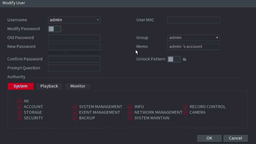
Figure 2.204
Step2 Check the box to enable Modify Password function. Enter old password and then enter new password twice.
- Password/confirm password: The password ranges from 8 to 32 digitals. It can contain letters, numbers and special characters (excluding “‘”,”””,“•”,”;”,”&”) . The password shall contain at least two categories. Usually we recommend the strong password.
For the user of account authority, it can modify the password of another user.
- STRONG PASSWORD RECOMMENDED-For your device own safety, create a strong password of your own choosing. We also recommend you change your password periodically especially in the high security system.
Check the box to enable Unlock Pattern function, click
Step3 Enter the Unlock Pattern interface to set. See Figure 2.205.
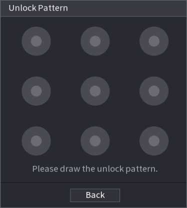
Figure 2.205
Stepl Select Main Menu ^ ACCOUNT ^ Group. The Group interface is displayed. See Figure 2.206.
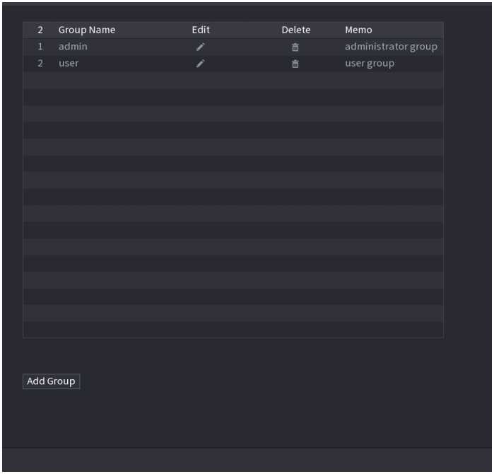
Step2 Click Add Group button in Figure 2.206. The Add Group interface is displayed. See Figure 2.207.
Step3 Enter group name and then input some memo information if necessary. Check the box to select authorities.
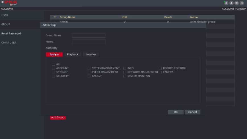
Figure 2.207
![]()
Click I
to modify the corresponding group information, click
to delete the group.
You can set security questions and answers. After you successfully answered security questions, you can reset admin account password.
This function is for admin user only.
Step1 Select Main Menu ■> ACCOUNT ^ PASSWORD RESET. The PASSWORD RESET interface is
displayed. See Figure 2.208.
Reset Password
0 Enable
Email Address
Security Question
Please set a security question sothatyoucanfindthe password of admin again.
Question 1 Whatisyourfavoritechildren’ s book?
Answer
Question 2 What was the first name of your first boss?
Answer
Question 3 What is the name of your favorite fruit?
Answer
Apply Back
Figure 2.208
Step2 Check the box to enable Reset password function.
This function is enabled by defaul
Step3 Input proper security questions and answers.
Step4 Click OK, after you successfully set security questions, you can answer the security questions to reset admin password.
When the camera from the third party is connected with the NVR via the ONVIF user, use the verified ONVIF account to connect to the NVR. Here you can add/delete/modify user.
The default ONVIF user is admin. It is created after you initialize the NVR.
For some series product, the ONVIF user password is modified when you are
initializing the admin password.
Step1 Select Main Menu ^ ACCOUNT ^ ONVIF User. The ONVIF User interface is displayed. See Figure 2.209.
Figure 2.209
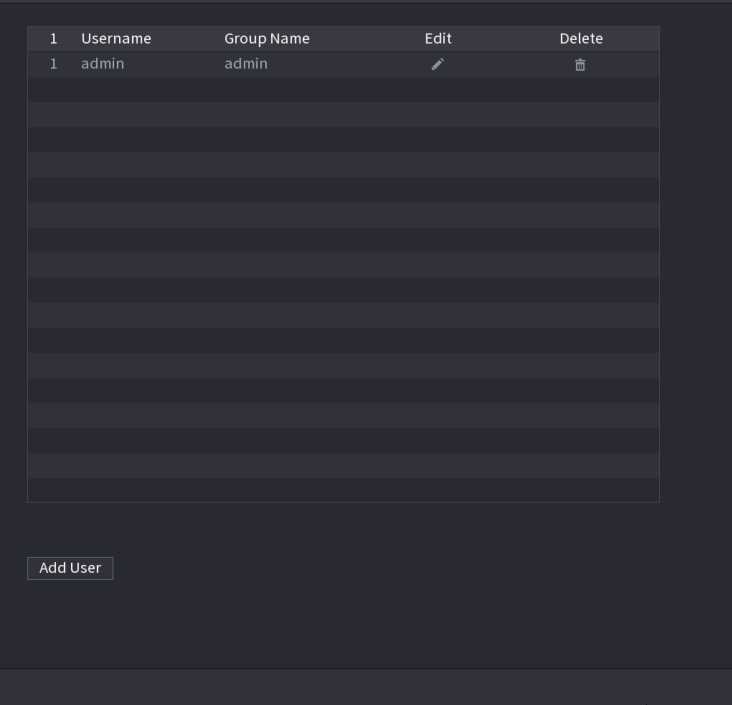
Step2 Click Add User button. The Add User interface is displayed. See Figure 2.210.
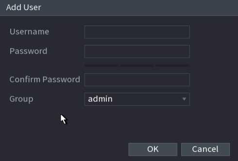
Figure 2.210
Step3 Set username, password and then select group from the dropdown list.
Step4 Click OK to complete setup.
Click
to modify corresponding user information, click
to delete current user.
![]()
![]()
![]()
You can configure the display effect such as displaying time title and channel title, adjusting image transparency, and selecting the resolution.
Step1 Select Main Menu ^ DISPLAY ^ Display. The Display interface is displayed. See Figure 2.211.
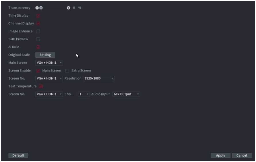
Figure 2.211
Step2 Configure the settings for the display parameters.
| Parameter | Description |
| T ransparency | Set the transparency of the local menu of the NVR device. The higher the transparency, the more transparent the local menu. |
| Time Display/Channel Display | Select the check box and the date and time of the system will be displayed in the preview screen. |
| Image Enhance | Select the check box to optimize the preview image edges. |
| IVS Rule | Select the check box to display the IVS rules in the preview interface. |
| This function is for some series products only. | |
| Original Scale | Click Setting and select the channel to restore the corresponding channel image to the original scale. |
| Main Screen | Select VGA+HDMI1 or HDMI2.
Different devices display different contents. See the actual situation. |
| Screen Enable | Select the check box to enable this screen. The image can only be displayed when the screen is enabled. |
| Test Temperature | Check the box to test the object temperature, including trace the high/low temperature. |
| Resolution | Support 1920×1080, 1280×1024(default), 1280×720. |
| Screen No. | Enter the screen number you want to set the audio input. |
| Channel | Select the channel number. |
| Audio Input | Select from audio 1, audio 2 and mix output. |
Step3 Click Apply.
You can configure a tour of selected channels to repeat playing videos. The videos display in turn according to the channel group configured in tour settings. The system displays one channel group for a certain period and then automatically changes to the next channel group.
Stepl Select Main Menu ^ DISPLAY ^ Tour. The Tour interface is displayed. See Figure 2.212.

![]()
![]()
![]()
![]()

On the top right of the live view screen, use the left mouse button or press Shift to switch, between
image switching
is allowed) and
(image switching is not allowed) to turn on/off the tour function. On the navigation bar, click
to
enable the tour and click
to disable it.
Step2 Configure the settings for the tour parameters.
| Parameter | Description |
| Enable | Enable tour function. |
| Interval (Sec.) | Enter the amount of time that you want each channel group displays on the screen. The value ranges from 5 seconds to 120 seconds, and the default value is 5 seconds. |
| Video Detect, Alarm | Select the View 1 or View 8 for Motion Detect tour and Alarm Tour (system alarm events). |
| Window Split | In the Window Split list, select View 1, View 4, View 8, or other modes that are supported by the Device. |
| Channel Group | Display all channel groups under the current Window Split setting.
Group channel, select the channels to form a group, and then click Save.
channel group, and then click Delete.
channel group and then click Modify or double-click on the group. The Modify Channel Group dialog box is displayed. You can regroup the channels.
of channel group. |
Step3 Click Apply to save the settings.
You can set customized video split mode.
This function is for some series products. Refer to the actual product for detailed information.
Device max. supports 5 customized videos.
Step1 Select Main Menu ^ DISPLAY ^ Custom Split. The Custom Split interface is displayed. See Figure 2.213.
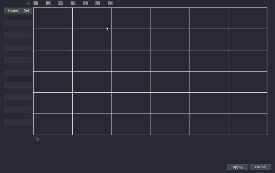
![]()
Figure 2.213
to select basic mode.
System adopts the basic window mode as the new window name. For example, if you select the 8-display mode, the default name is Split8. In regular mode, drag the mouse in the preview frame; you can merge several small windows to one window so that you can get you desired split mode. See Figure 2.214.
After merge the window, system adopts the remaining window amount as the new name such as Split6.
![]()
![]()
![]()
Select the window you want to merge (red highlighted), click
to cancel the merge to restore the basic
• Click
to delete the customized window mode.

Name splits
Apply Cancel
Figure 2.214
After the setu p, you ca n go to the preview window, right cl i ck mouse a nd then select Custom Split. See Figure 2.215.
Main Menu
Playback PT I
View 1
View 4
ViewS
View 9
i”
View 16
View 25
View 36
View 64
Sequence
Smart Tracking
Custom Split
’ Splits
Add IP Ca mera
Fisheye
Manual
Preview Mode
AuloFdCUS
The audio function is to manage audio files and set schedule play function. It is to realize audio broadcast activation function.
This function is for some series product only.
You can add audio files, listen to audio files, rename and delete audio files, and configure the audio volume.
Step1 Select Main Menu ^ AUDIO ^ File Manager. The File Manager interface is displayed. See Figure 2.216.
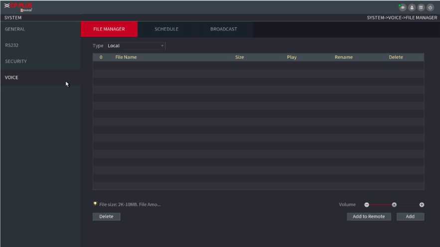
Figure 2.216
The Add interface is displayed. See Figure 2.217.
NVR supports USB port to import audio file only.
Add
sdbl(USBUSB) * Refresh Format
Device Name
Total Space
Free Space
286.10 MB
249.24 MB
Address
| Name | Size | Type | Delete | |
| ■ a | Folder | a | ||
| ® NVR_chl_main_20190921142147_2… | 2.25 MB | File | a | |
| g SmartPlayer.exe | 2.20 MB | File | a | |
| g XVR_chl_jpg_20191021162552.jpg | 5.0 KB | Fite | a | |
| XVR_chl_main_20191021084552_2… | 11.79 MB | File | a | * |
OK Cancel
New Folder
Figure 2.217
Step3 Select the audio file and then click Import.
System supports MP3 and PCM audio format.
Step4 Click OK to start importing audio files from the USB storage device.
If the importing is successful, the audio files will display in the File Manager interface.
You can configu re the setti ngs to play the a ud i o fi les d u ri ng the defined ti me per iod .
Step1 Select Main Menu ^ AUDIO ^Schedule. The Schedule interface is displayed. See Figure 2.218.
| Period | File Name | Interval | Repeat
0 |
Output | |||
| Min. | |||||||
| 00 :00 | – 24 :00 | None |
60 |
Mic | |||
| 00 :00 | – 24 :00 | None | <| 60 | Min. | 0 | Mic | |
| 00 :00 | – 24 :00 | None | ▼ ] 60 | Min. | 0 | Mic | ▼ |
| 00 :00 | 24 :00 | None | ’ 60 | Min. | 0 | Mic | ▼ |
| 00 :00 | – 24 :00 | None | * 60 | Min. | 0 | Mic | |
| 00 :00 | – 24 :00 | None | ▼| 60 | Min. | 0 | Mic | |
Apply Cancel
Figure 2.218
Step2 Configure the settings for the schedule parameters.
| Parameter | Description |
| Period | In the Period box, enter the time. Select the check box to enable the settings.
You can configure up to six periods. |
| File Name | In the File Name list, select the audio file that you want to play for this configured period. |
| Interval | In the Interval box, enter the time in minutes for how often you want to repeat the playing. |
| Repeat | Configure how many times you want to repeat the playing in the defined period. |
| Output | Includes two options: MIC and Audio. It is MIC by default. The MIC function shares the same port with talkback function and the latter has the priority. |
| Some series products do not have audio port. The actual | |
| product shall prevail. |
The finish time for audio playing depends on audio file size and the configured interval.
Playing priority: Alarm event ^ Audio talk ^ Trial listening ^ Schedule audio file.
Step3 Click Apply to complete the settings.
System can broadcast to the camera, or broadcast to a channel group.
Step1 Select Mani Menu ^ AUDIO ^ BROADCAST. The BROADCAST interface is displayed. See Figure 2.219.
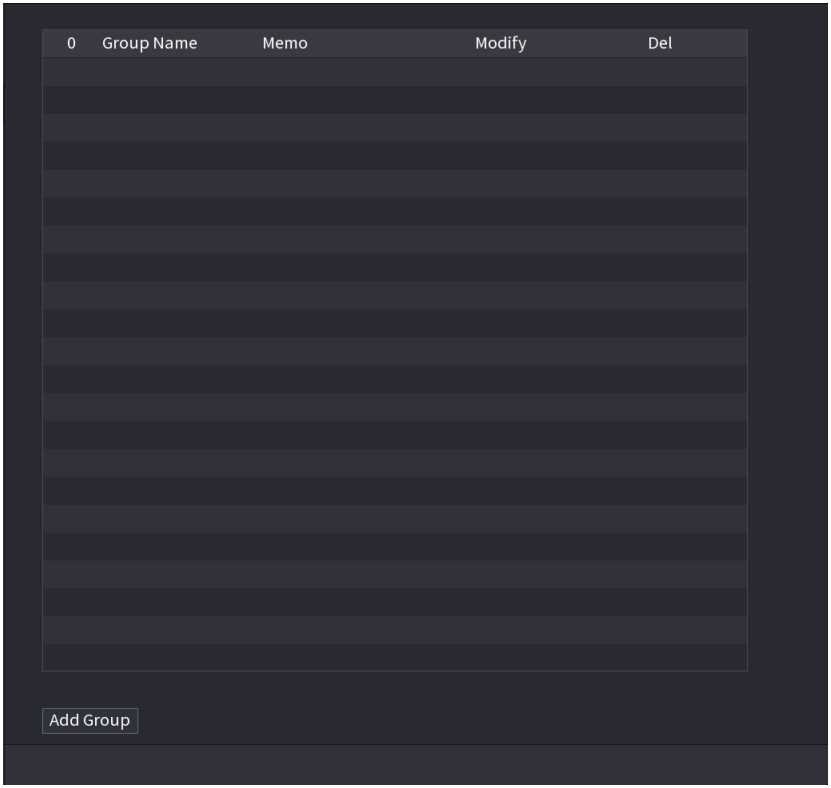
Figure 2.219
The Add Group interface is displayed. See Figure 2.220.
| Add Group | |||||||
| Group Name | |||||||
| Cha | All | ||||||
| ri 1 | □ 2 | □ 3 | Fl 4 | □ 5 | J 6 | □ 7 | □ 8 |
| □ 9 | □ 10 | □ 11 | □ 12 | □ 13 | 14 | □ 15 | □ 16 |
| n 17 | 18 | □ 19 | □ 20 | □ 21 | Z 22 | □ 23 | □ 24 |
| 25 | □ 26 | □ 27 | □ 28 | □ 29 | 30 | □ 31 | □ 32 |
| □ 33 | □ 34 | □ 35 | □ 36 | □ 37 | Z 38 | □ 39 | □ 40 |
| □ 41 | □ 42 | □ 43 | □ 44 | 45 | 46 | □ 47 | □ 48 |
| 49 | n so | Fl 51 | n 52 | □ 53 | 54 | □ 55 | □ 56 |
| 57 | □ 58 | □ 59 | □ 60 | 61 | 62 | □ 63 | □ 64 |
| Save | Cancel | ||||||
Figure 2.220
Step3 Input group name and select one or more channels.
Step4 Click Save button to complete broadcast group setup.
![]()
![]()
![]()
On the broadcast interface, click
to change group setup, click to delete group.
on the navigation bar, device
| • Select a group name and then click | <1^ | to begin broadcast. See Figure 2.221. |
|---|
After complete broadcast setup, on the preview interface and then click pops up broadcast dialogue box.
1 Group Name Memo
Modify
Del
1 test
Channel DIO D13
Add Group
Figure 2.221
After you inserted the USB device, system can auto detect it and pop up the following dialogue box. It allows you to conveniently backup file, log, configuration or update system. See Figure 2.222.
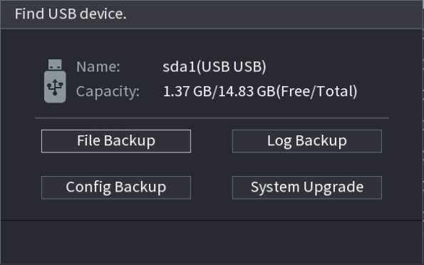
Figure 2.222
- When you see corresponding dialogue box “System is shutting down…” Do not click power on-off button directly.
- Do not unplug the power cable or click power on-off button to shutdown device directly when device is running (especially when it is recording.)
- Shut down the device and then unplug the power cable before you replace the HDD.
From the main menu (Recommended)
![]()
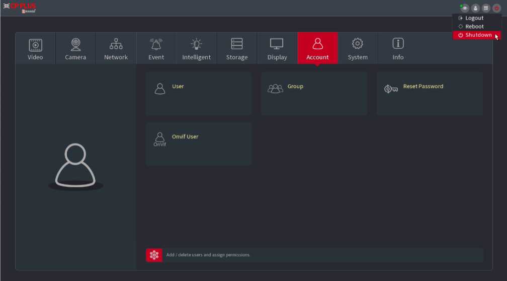
at the top right corner. See Figure 2.223.
Figure 2.223
Step2 Select Shutdown.
Draw the unlock pattern or input password first if you have no authority to shut down. See Figure 2.224 and Figure 2.225.
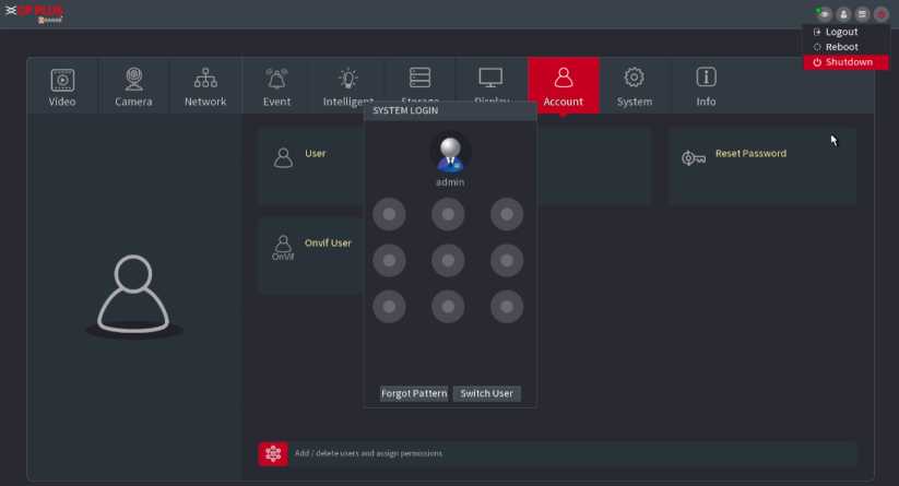
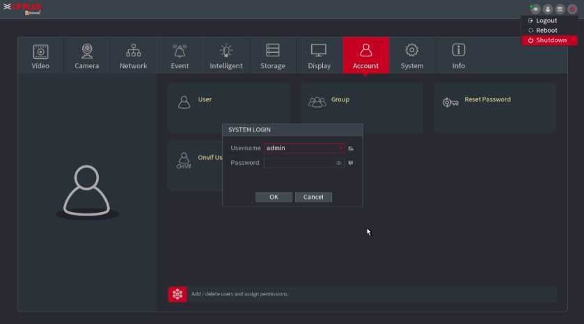
Figure 2.225
o Press the power button on the remote for at least 3 seconds. o Press the power button at the rear panel of the device.
The system can automatically backup video file and resume previous working status after power failure.
![]()
The interfaces in the Manual are used for introducing the operations and only for reference. The actual interface might be different dependent on the model you purchased. If there is inconsistency between the Manual and the actual product, the actual product shall govern.
The Manual is a general document for introducing the product, so there might be some functions described for the Device in the Manual does not apply to the model you purchased.
Besides Web, you can use our KVMS Pro to login the device. For detailed information, refer to KVMS Pro user’s manual.
The factory default IP of the Device is 192.168.1.245.
The Device supports monitoring on different browsers such as Safari, Firefox, Google to perform the functions such as multi-channel monitoring, PTZ control, and device parameters configurations.
Step1 Check to make sure the Device has connected to the network.
Step2 Configure the IP address, subnet mask and gateway for the PC and the Device.
Step3 On your PC, check the network connection of the Device by using “ping ***.******.***”. Usually the return value of
TTL is 255.
Step1 Open the browser, enter the IP address of the Device, and then press Enter. The Login in dialog box is displayed. See
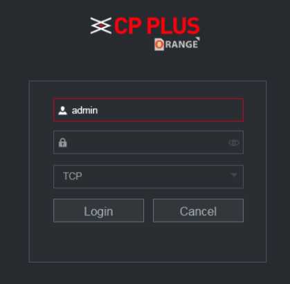
Figure 3.1
Step2 Enter the username and password.
The default administrator account is admin. The password is the one that was configured during initial settings. To security your account, it is recommended to keep the password properly and change it regularly.
Click
to display the password
• If you forget the password, click Forgot Password to reset the password.
Step3 Click Login.
You can reset the password by the following methods when you forget the password for admin account.
- If the password reset function is enabled, you can use mobile phone to scan the QR code on the local interface or web interface to reset the password.
- If the password reset function is disabled, the system prompts indicating password resetting function is disabled. To reset the password, try either of the following ways:
o Login the web with other user account to enable the password reset function.
o Go to local interface to reset the password.
Step1 Login the Web of the Device.
The Login in dialog box is displayed. See Figure 3.2.
2 range’
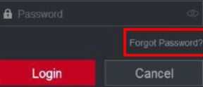
- igure 3.2
The Reset Password interface is displayed.
Step 3 Click OK.
The reset type interface is displayed. See Figure 3.3.

Figure 3.3
Step4 Follow the onscreen instructions to scan the QR code and get the security code.

You can get the security code twice by scanning the same QR code. If you need to get the security code once again, refresh the interface.
Use the security code received in your email box to reset the password within 24 hours; otherwise the security code becomes invalid.
Wrong security code entrance up to five times will cause the security code locked for five minutes. After five minutes, you can continue to use this security code.
Step5 In the Security code box, enter the security code received in your reserved email box.
Step6 Click Next. The new password resetting interface is displayed. See Figure 3.4.
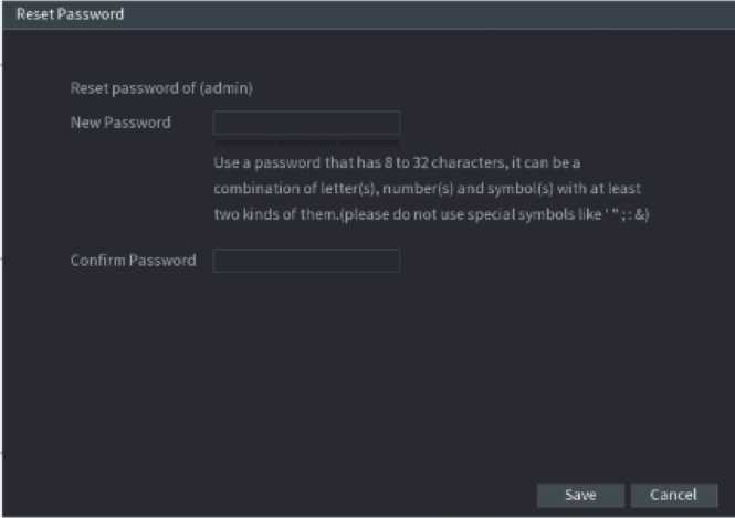
Figure 3.4
Step7 In the Password box, enter the new password and enter it again in the Confirm Password box.
![]()
The new password can be set from 8 characters through 32 characters and contains at least two types from number, letter and special characters (excluding”‘”, “””,”;”,”:” and “&”).
Step8 Click Save. The password resetting is started.
After resetting is completed, a pop-up message is displayed to indicate the result and you will see the login interface is displayed. Then you can use the new password to login the web.
After you have logged in the Web, the main menu is displayed. See Figure 3.5.
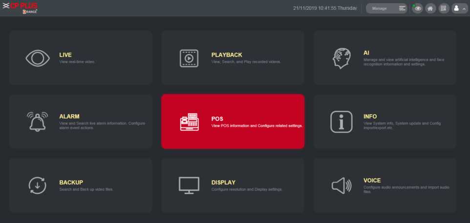
Figure 3.5
| 7 | None | Includes eight function tiles: LIVE, PLAYBACK, AI, ALARM, POS, OPERATION, BACKUP, DISPLAY, and AUDIO. Click each tile to open the configuration interface of the tile.
LIVE : You can perform the operations such as viewing real-time video, configuring channel layout, setting PTZ controls, and using smart talk and instant record functions if needed. PLAYBACK: Search for and play back the recorded video saved on the Device. ALARM : Search for alarm information and configure alarm event actions. AI : Configure and manage artificial intelligent events. It includes smart search, parameters, and database. POS : View POS information and configure related settings. OPERATION: View system information, import/export system configuration files, or update system. BACKUP: Search and back up the video files to the local PC or external storage device such as USB storage device. DISPLAY: Configure the display effect such as displaying content, image transparency, and resolution, and enable the zero-channel function. AUDIO: Manage audio files and configure the playing schedule. The audio file can be played in response to an alarm event if the voice prompts function is enabled. |
- DHCP: DHCP (Dynamic Host Configuration Protocol) is a network protocol. It is one of the TCP/IP protocol cluster. It is principally used to assign temporary IP addresses to computers on a network.
- DDNS: DDNS (Dynamic Domain Name Server) is a service that maps Internet domain names to IP addresses. This service is useful to anyone who wants to operate a server (web server, mail server, ftp server and etc.) connected to the internet with a dynamic IP or to someone who wants to connect to an office computer or server from a remote location with software.
- eSATA: eSATA (External Serial AT) is an interface that provides fast data transfer for external storage devices. It
is the extension specifications of a SATA interface.
- GPS: GPS (Global Positioning System) is a satellite system, protected by the US military, safely orbiting thousands of kilometers above the earth.
- PPPoE: PPPoE (Point to Point Protocol over Ethernet) is a specification for connecting multiple computer users on an Ethernet local area network to a remote site. Now the popular mode is ADSL and it adopts PPPoE protocol.
- Wi-Fi: Wi-Fi is the name of a popular wireless networking technology that uses radio waves to provide
wireless high-speed Internet and network connections. The standard is for wireless local area networks (WLANs). It is like a common language that all the devices use to communicate to each other. It is actually IEEE802.11, a family of standard The IEEE (Institute of Electrical and Electronics Engineers Inc.)
- 3G: 3G is the wireless network standard. It is called 3G because it is the third generation of cellular telecom
standards. 3G is a faster network for phone and data transmission and speed Is over several hundred kbps. Now there are four standards: CDMA2000, WCDMA, TD-SCDMA and WiMAX.
- Dual-stream: The dual-stream technology adopts high-rate bit stream for local HD storage such as QCIF/CIF/2CIF/DCIF/4CIF encode and one low-rate bit stream for network transmission such as QCIF/CIF encode. It can balance the local storage and remote network transmission. The dual stream can meet the difference band width requirements of the local transmission and the remote transmission. In this way, the local transmission using high-bit stream can achieve HD storage and the network transmission adopting low bit stream suitable for the fluency requirements of the 3G network such as WCDMA, EVDO, TD-SCDMA.
- On-off value: It is the non-consecutive signal sampling and output. It includes remote sampling and remote
output. It has two statuses: 1/0.
Cybersecurity is more than just a buzzword: it’s something that pertains to every device that is connected to the internet. IP video surveillance is not immune to cyber risks, but taking basic steps toward protecting and strengthening networks and networked appliances will make them less susceptible to attacks. Below are some tips and recommendations on how to create a more secured security system.
- Mandatory actions to be taken for basic equipment network security:
- Use Strong Passwords
- Please refer to the following suggestions to set passwords:
- The length should not be less than 8 characters;
- Include at least two types of characters; character types include upper- and lower-case letters, numbers and symbols;
- Do not contain the account name or the account name in reverse order;
- Do not use continuous characters, such as 123, abc, etc.
- Do not use overlapped characters, such as 111, aaa, etc.
- Update Firmware and Client Software in Time
- According to the standard procedure in Tech-industry, we recommend keeping your equipment (such as NVR, DVR, IP camera, etc.) firmware up to date to ensure the system is equipped with the latest security patches and fixes. When the equipment is connected to the public network, it is recommended to enable the “auto-check for updates” function to obtain timely information of firmware updates released by the manufacturer.
- We suggest that you download and use the latest version of client software.
- “ Nice to have” recommendations to improve your equipment network security:
- Physical Protection
a. We suggest that you perform physical protection to equipment, especially storage devices. For example, place the equipment in a special computer room and cabinet, and implement well-done access control permission and key management to prevent unauthorized personnel from carrying out physical contacts such as damaging hardware, unauthorized connection of removable equipment (such as USB flash disk, serial port), etc.
- Change Passwords Regularly
a. We suggest that you change passwords regularly to reduce the risk of being guessed or cracked.
- Set and Update Passwords Reset I nformation Timely
a. The equipment supports password reset function. Please set up related information for password reset in time, including the end user’s mailbox and password protection questions. If the information changes, please modify it in time. When setting password protection questions, it is suggested not to use those that can be easily guessed.
- Enable Account Lock
a. The account lock feature is enabled by default, and we recommend you keep it on to guarantee the account security. If an attacker attempts to log in with the wrong password several times, the corresponding account and the source IP address will be locked.
- Change Default HTTP and Other Service Ports
a. We suggest you change default HTTP and other service ports into any set of numbers between 1024~65535, reducing the risk of outsiders being able to guess which ports you are using.
- Enable HTTPS
a. We suggest you enable HTTPS, so that you visit Web service through a secure communication channel.
- Enable Whitelist
a. We suggest you enable whitelist function to prevent everyone, except those with specified IP addresses, from accessing the system. Therefore, please be sure to add your computer’s IP address and the accompanying equipment’s IP address to the whitelist.
- MAC Address Binding
a. We recommend you bind the IP and MAC address of the gateway to the equipment, thus reducing the risk of ARP spoofing.
- Assign Accounts and Privileges Reasonably
a. According to business and management requirements, reasonably add users and assign a minimum set of permissions to them.
- Disable Unnecessary Services and Choose Secure Modes
If not needed, it is recommended to turn off some services such as SNMP, SMTP, UPnP, etc., to reduce risks. If necessary, it is highly recommended that you use safe modes, including but not limited to the following services:
- SNMP: Choose SNMP v3, and set up strong encryption passwords and authentication passwords.
- SMTP: Choose TLS to access mailbox server.
- FTP: Choose SFTP and set up strong passwords.
- AP hotspot: Choose WPA2-PSK encryption mode and set up strong passwords.
- Audio and Video Encrypted Transmission
- If your audio and video data contents are very important or sensitive, we recommend that you use encrypted transmission function, to reduce the risk of audio and video data being stolen during transmission.
- Reminder: encrypted transmission will cause some loss in transmission efficiency.
- Secure Auditing
- Check online users: we suggest that you check online users regularly to see if the device is logged in without authorization.
- Check equipment log: By viewing the logs, you can know the IP addresses that were used to log in to your devices and their key operations.
- Network Log
a. Due to the limited storage capacity of the equipment, the stored log is limited. If you need to save the log for a long time, it is recommended that you enable the network log function to ensure that the critical logs are synchronized to the network log server for tracing.
- Construct a Safe Network Environment
In order to better ensure the safety of equipment and reduce potential cyber risks, we recommend:
- Disable the port mapping function of the router to avoid direct access to the intranet devices from external network.
- The network should be partitioned and isolated according to the actual network needs.
If there are no communication requirements between two sub networks, it is suggested to use VLAN, network GAP and other technologies to partition the network, so as to achieve the network isolation effect.
- Establish the 802.1x access authentication system to reduce the risk of unauthorized access to private networks.
q that is needed for all
channels in device during alarm video recording (including motion detection).
c
qT = Emi xa% (4)
i=1
In the formula: a% means alarm occurrence rate
time.
The IVS function environment shall meet the following requirements:
• The object total size shall not be more than 10% of the whole video.
• The object size on the video shall not be more than 10pixels* *10 pixels. The abandoned object size shall be
more than 15pixels*15 pixels (CIF resolution). The object width shall not be more than 1/3 of the video height and width. The recommended height is 10% of the video.
• The object and the background brightness different shall be more than 10 grey levels.
• The object shall remain on the video for more than 2 seconds. The moving distance is larger than its own width
and shall not be smaller than 15pixels (CIF resolution).
• The surveillance environment shall not be too complicated. The IVS function is not suitable for the environment of too many objects or the changing light.
• The surveillance environment shall not contain glasses, reflection light from the ground, and water. Free of tree branches, shadow, mosquito and bugs. Do not use the IVS function in the backlight environment, avoid direct sunlight.
Step1 Select Main Menu ■> AI ■> PARAMETERS ■> IVS.
The IVS interface is displayed. See Figure 2.109.
