How To Setup Dahua Access Control The DHI-ASC3202B provides a single-interface access control solution that is accessible anywhere there is an internet connection. The controller has two modes: the main mode and the sub mode. The main mode allows the controller to serve as central management for all access control devices in a building or area. The sub mode allows additional controllers to be pooled into the main controller device list and networks card readers together.
Each controller controls up to two (2) doors but can be scalable up to 40 doors. The controller can be powered via PoE+ (IEEE802.3at), added to DMSS for remote door control, and ONVIF compliant to allow for third-party reader management.
Access Controller
> Bulit-in Web server, features main and sub control modes.
> The main control mode offers access control Platform functions,can connect with and manage up to 19 sub controllers. The sub-control modes can be added to multiple platforms.
> Supports 1000 users, 3000 fingerprints, and 300,000 records.
> Accesses card readers through Wiegand and RS-485 protocols.
> Supports TCP and IP connection, and standard PoE.
> Supplies power to the lock through its 12 VDC output power supply, which has a maximum output current of 1000 mA.
> Supports configuring the hardware I/O port and exporting configuration diagrams.
> Retains stored data even while powered off.
Read Next : How to Access a CCTV System Over the Internet
| Information | |
|---|---|
| Default IP | 192.168.1.108 |
| Enter PINs | USERID#6-digit code# -> i.e: 1#123456# |
| Card + PINs | Card Swipe + 6-digit code# -> i.e: 123456# |
| Function | Web GUI (Main Control) |
SmartPSS Lite | DSS Pro |
|---|---|---|---|
| First Card Unlock | No | Yes | Yes |
| Interlock | No | No | No |
| Anti-pass | No | Yes | Yes |
| Multi-card Unlock | No | Yes | Yes |
| Holiday Door Schedule | Yes | Yes | No |
| Heat Alarm | Yes | No | No |
| HID26 card number | Yes | No | No |
| HID Facility Site Code | Yes | No | No |
| Import card number in bulk | Yes | No | No |
| Export card number in bulk | Yes | No | No |
How to Setup a DHI-ASC3202B
Description
This article will cover how to setup a DHI-ASC3202B
Prerequisites
- DHI-ASC3202B
- A Computer connected to the DHI-ASC3202B
- Dahua Configtool
- DMSS Mobile App
Video Instructions
Step by Step Instructions
Initialization via ConfigTool
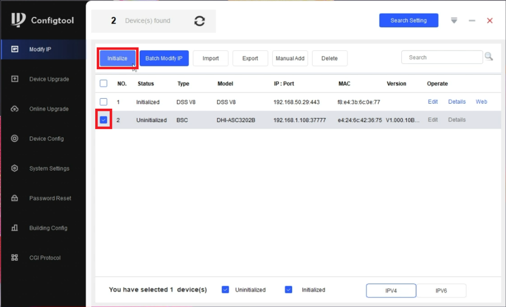
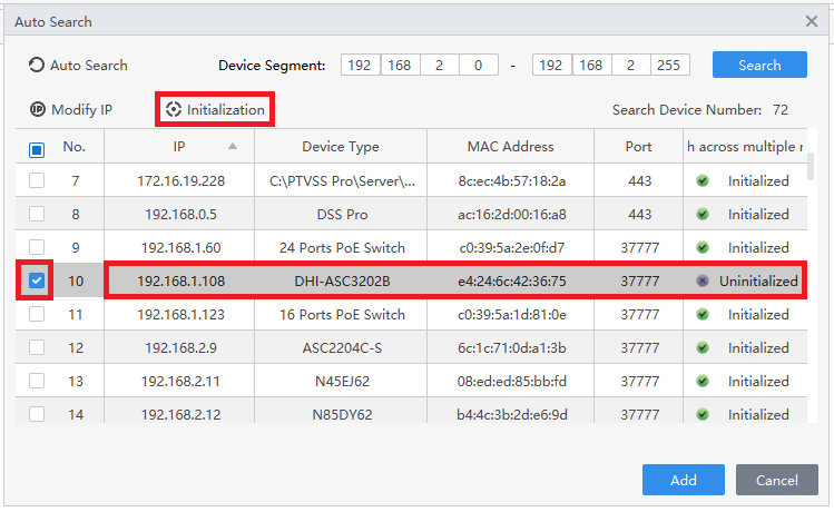
1. Open the Dahua ConfigTool.
Check the box next to the ASC3202B in the list.
Click on Initialize
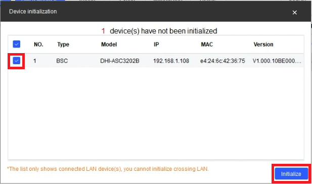
2. Make sure the box is checked next to the ASC3202B in the list.
Then click on Initialize
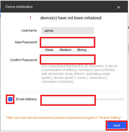
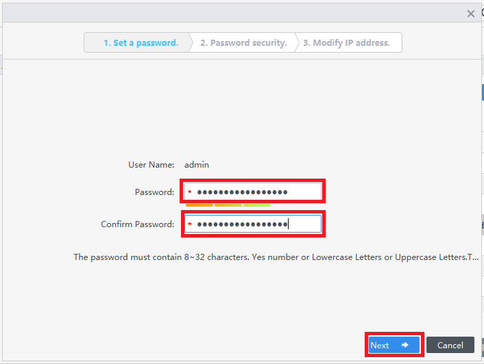
3. Enter a password that meets the criteria listed in the New Password and Confirm Password fields.
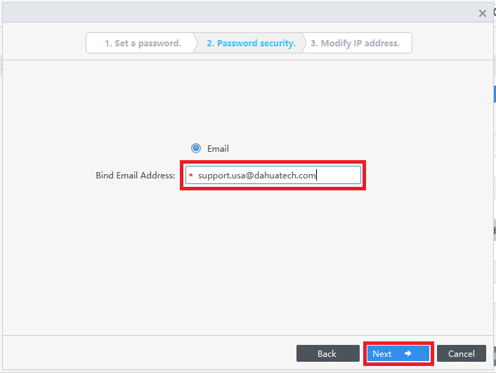
Then either check the box next to Email Address and enter an email address for password recovery, or uncheck the box to skip that step.
Click on Next
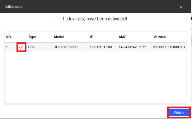
4. Once the ASC3202B has be successfully initialized, it will show a green check mark next to it in the list.
Click on Finish
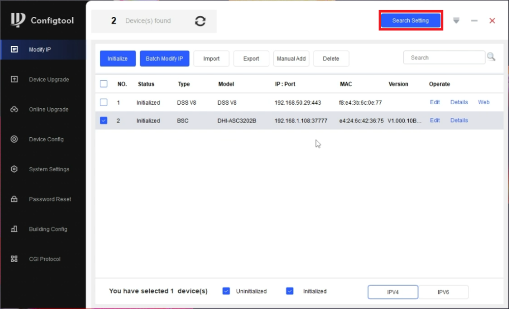
5. Click on Search Setting at the top
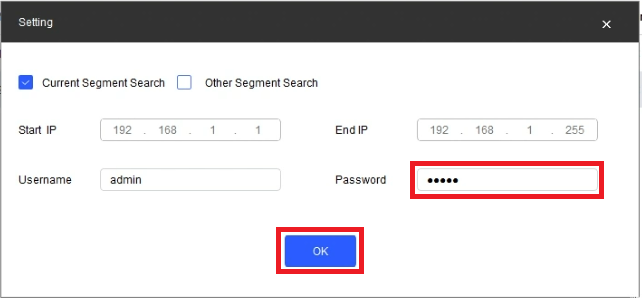
6. Enter the password you just set in Step 3 above, in the Password field.
Then click on OK
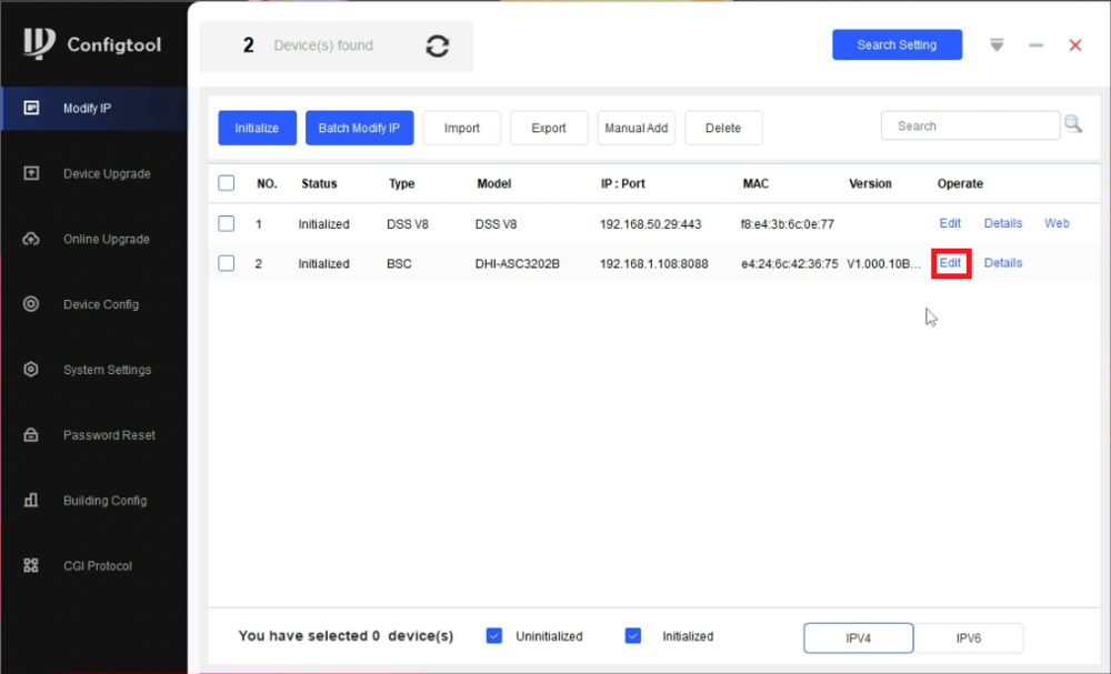
7. Select Edit next to the ASC3202B
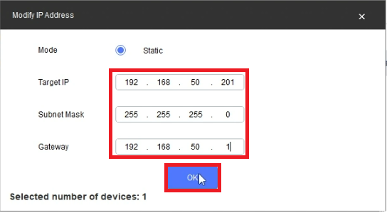
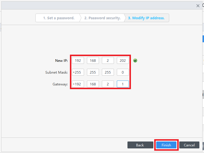
8. Enter the IP, Subnet Mask, and Gateway you want to set on the ASC3202B, making sure it’s an available IP address on the network.
Then click on OK
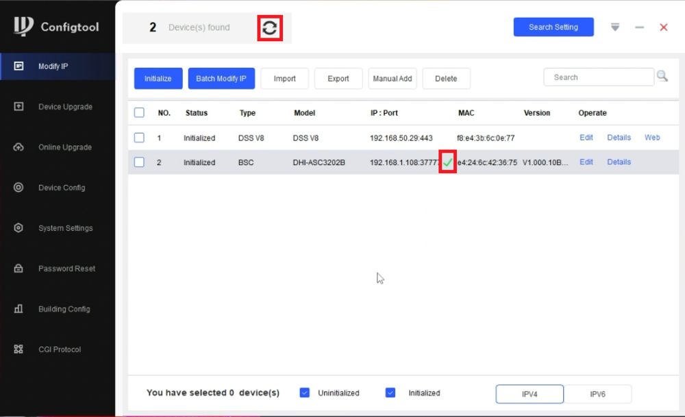
9. Once the IP scheme of the ASC3202B has changed successfully, you will see a green checkmark next to it in the list.
Click on the Refresh button at the top to varify the new IP address
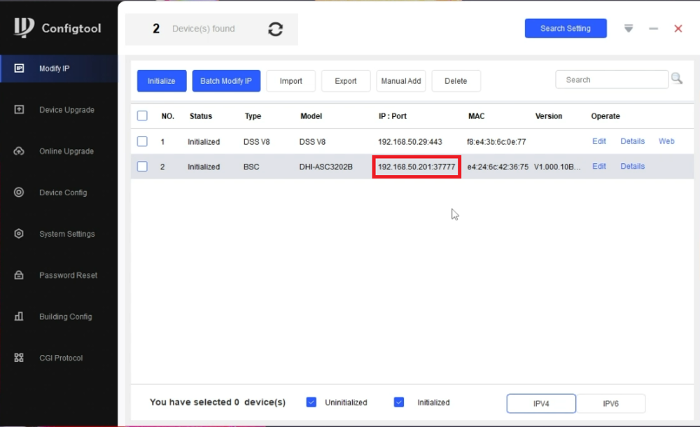
10. You will see the new IP address of the ASC3202B in the list
Initial Settings
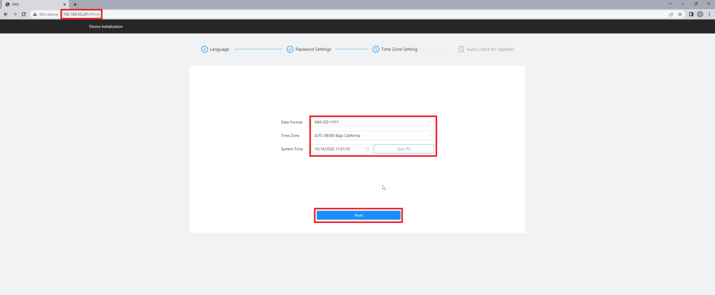
1. Open a web browser and enter the IP address of the ASC3202B in the URL field.
Once the browser connects to the ASC3202B, you will see the Initial Setup page.
Set the format of the date by choosing an option from the drop-down next to Date Format.
Set the timezone for your location by choosing an option from the drop-down next to Time Zone.
Manually set the date and time by selecting the option next to System Time or by pressing Sync PC to pull that information from the PC you are on.
Then click on Next at the bottom
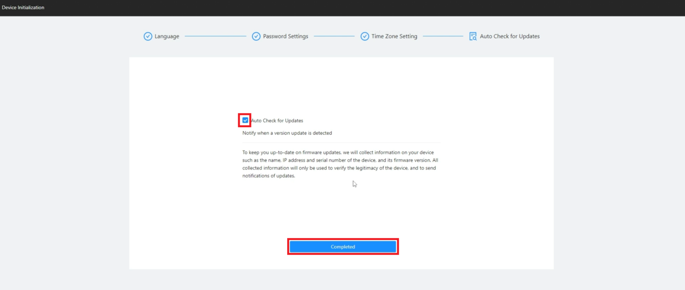
2. Check the box next to Auto Check for Updates if you want the ASC3202B to automatically upgrade its firmware when there is new firmware available, or uncheck it so that does not happen.
Then click on Completed
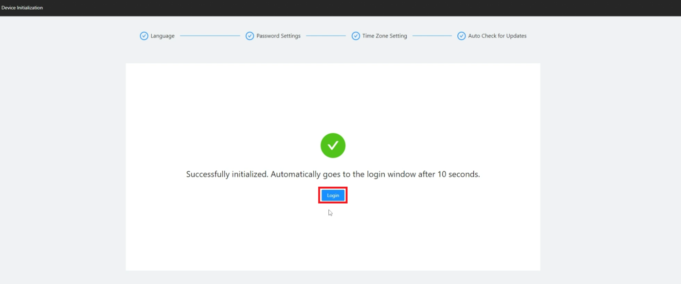
3. Either wait till the timer finishes counting down, or press the Login button
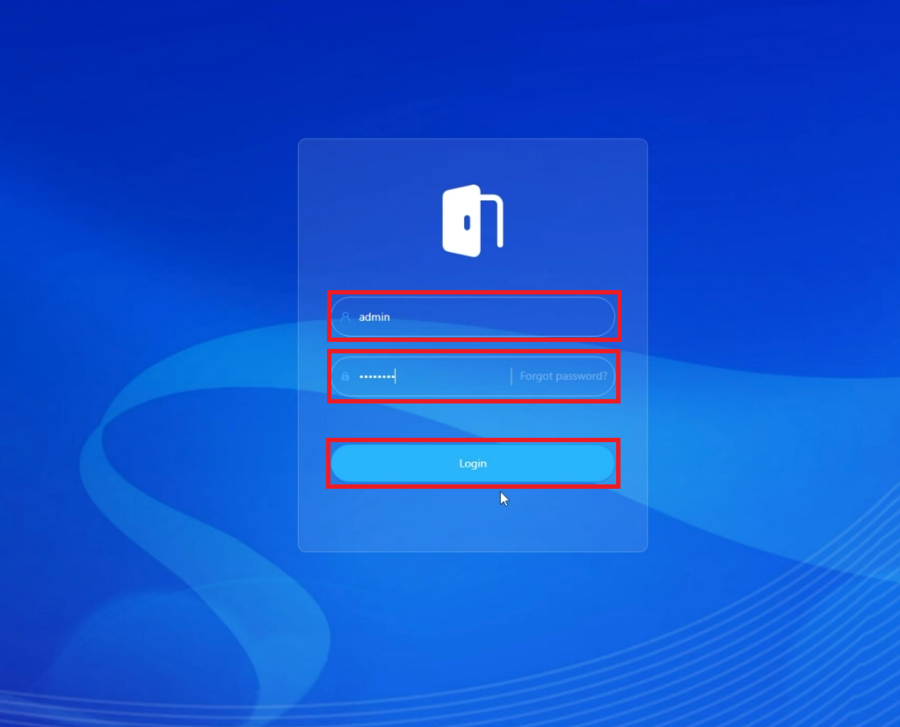
4. Enter “admin” in the Username field and then enter the password for the ASC3202B in the Password field.
Then click on Login
5. If this is a standalone access controller or the first of multiple ASC3202B units you are setting up, select Main Control.
If you already setup 1 Main ASC3202B controller and are setting this up as a secondary access controller on the same network, select Sub Control.
Then click on Next
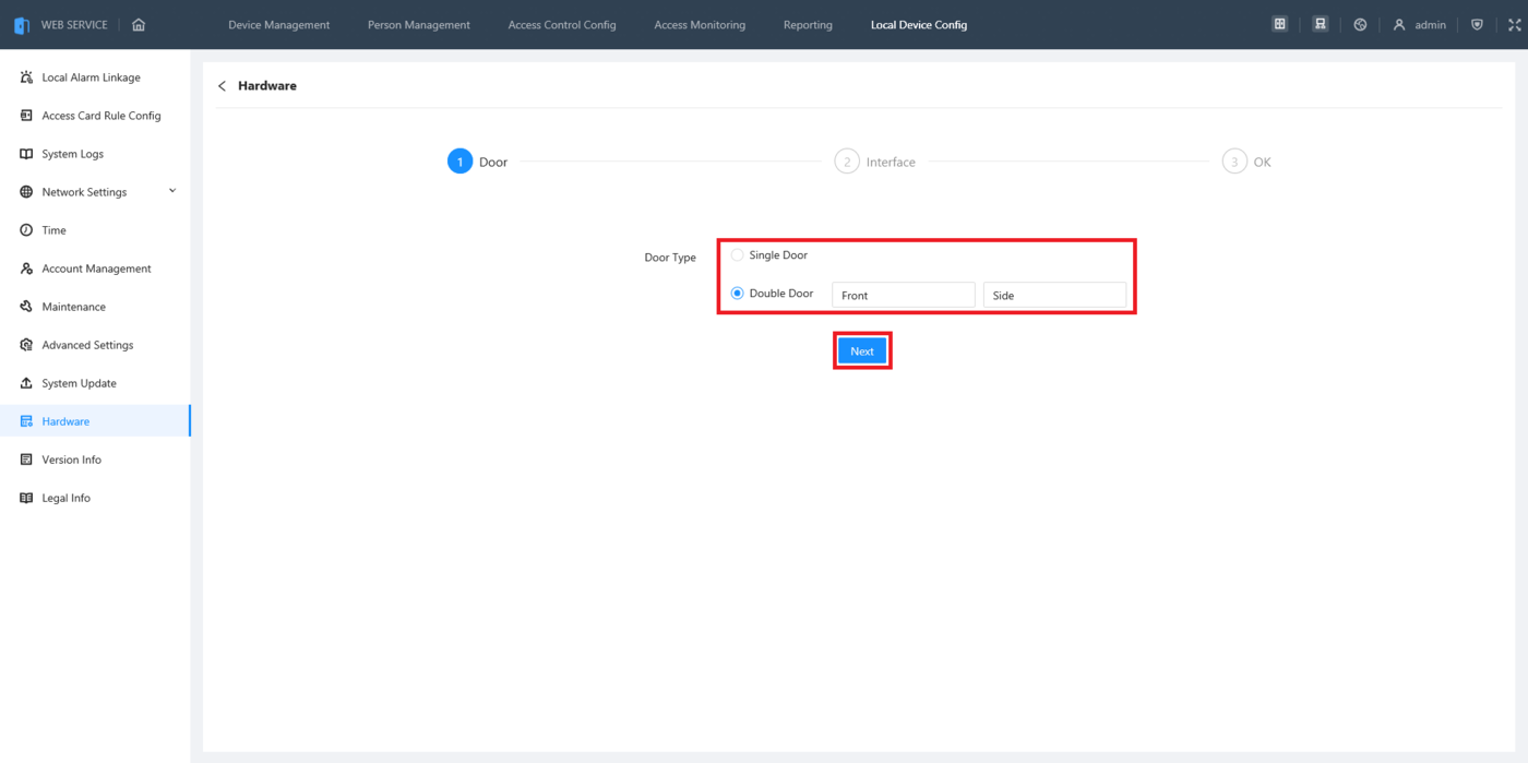
6. If you plan to use this as a single door access controller, select Single Door.
If you plan to use this as a 2 door access controller, select Double Door.
Type in the name(s) of the door(s) in the field(s) to the right.
Then click on Next
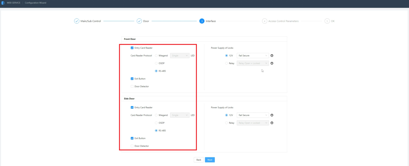
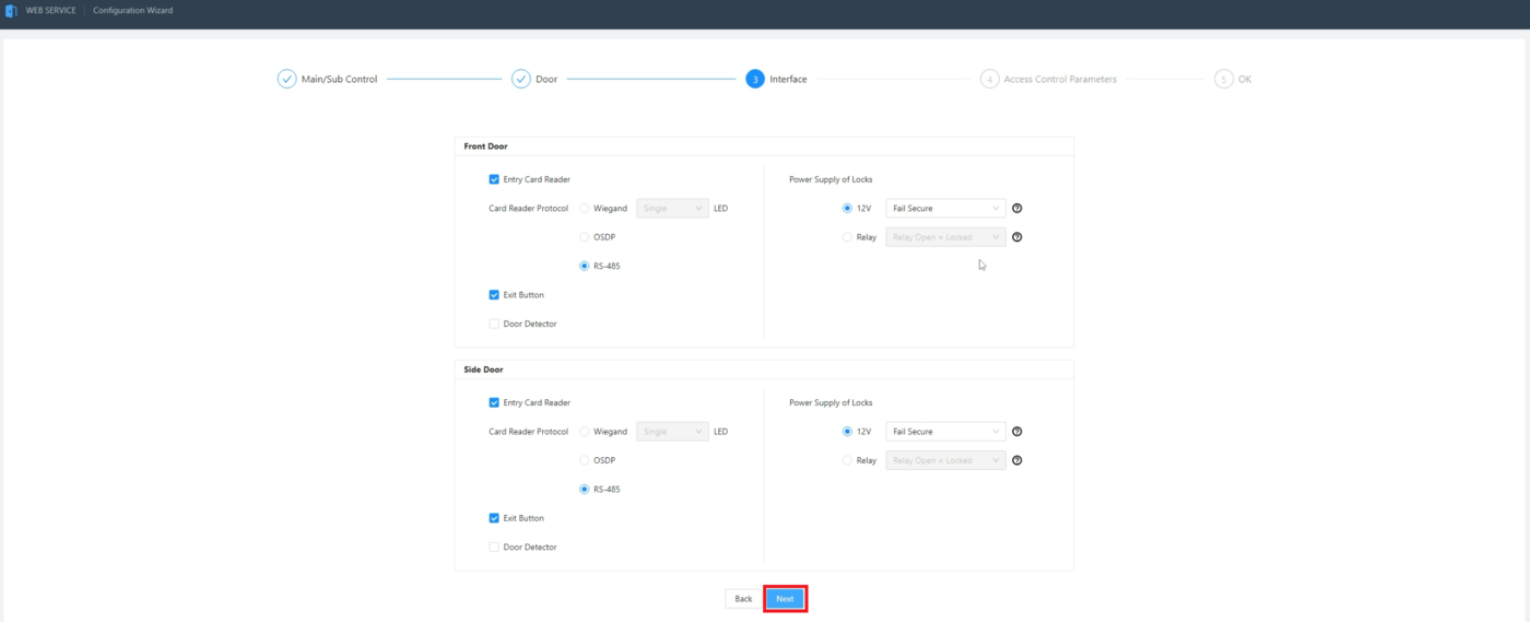
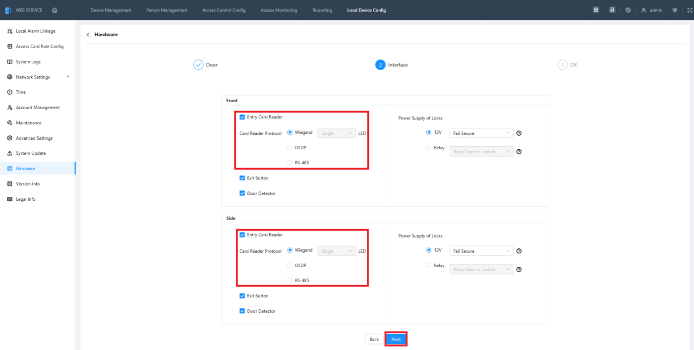
7. For each door, check the boxes for which devices you plan to wire up to the ASC3202B.
If you plan to have a card reader connected, check Entry Card Reader. Then choose the wiring connection the reader will use: Wiegand, OSDP, or RS-485. (OSDP is a more secure version of RS-485 and uses the same wiring.)
If you plan to have an exit button connected, check Exit Button.
If you plan to have a door sensor connected, check Door Detector
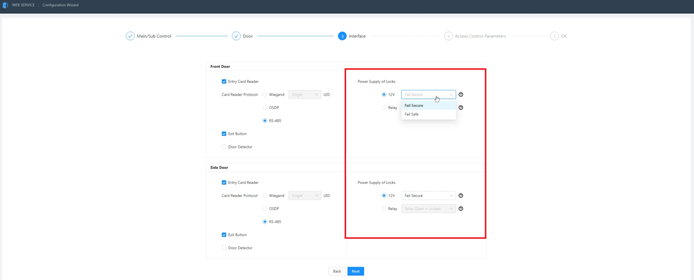
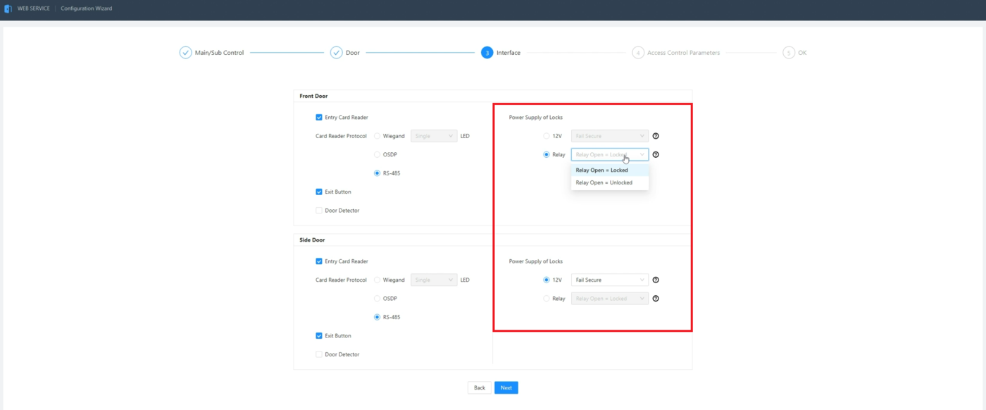
8. For each door, set how the locks will be powered.
If you plan to have the lock use the ASC3202B’s built in 12V power, select 12V. Then select either Fail Secure from the drop-down if it’s a normally closed lock or Fail Safe if it’s a normally open lock.
If you plan to have the lock use an external power supply, select Relay. Then select either Relay Open = Locked from the drop-down if it’s a normally closed lock or Relay Open = Unlocked if it’s a normally open lock.
9. When you are done making changes click on Next
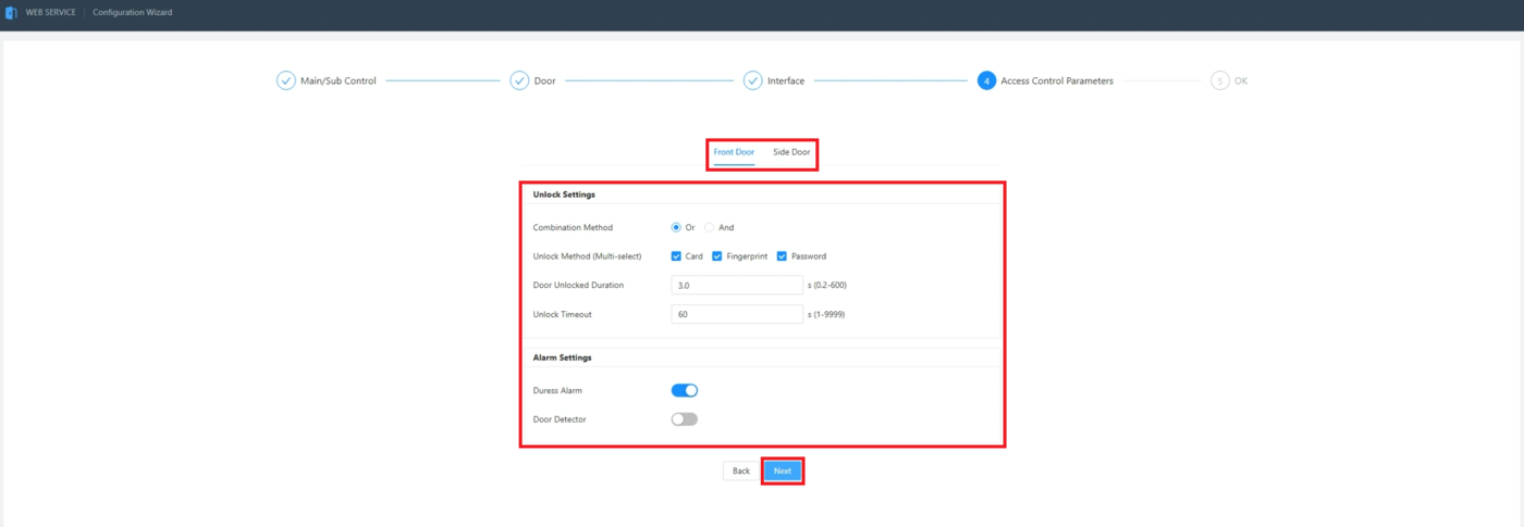
10. Set the settings for how you want each door to be unlocked and which alarms are enabled.
Set Combination Method to either Or if you want users to be able to unlock the door with just one method (Card, Fingerprint, or Password), or set it to And if you want users to have to use multiple methods.
Check the boxes next to Unlock Method (Multi-select) for which methods users will be allowed to use to unlock the door.
Enter the amount of time, in seconds, you want the door to stay unlocked once it has been unlocked in the field next to Door Unlocked Duration.
Enter the amount of time, in seconds, you want for when an alarm goes off if the door is kept open in the field next to Unlock Timeout.
Enable the slider next to Duress Alarm if you want to allow this door to trigger alarms with cards that are set as duress cards.
Enable the slider next to Door Detector if you want to allow alarms via a door sensor.
Repeat this process for the second door.
When you are done making changes click on Next
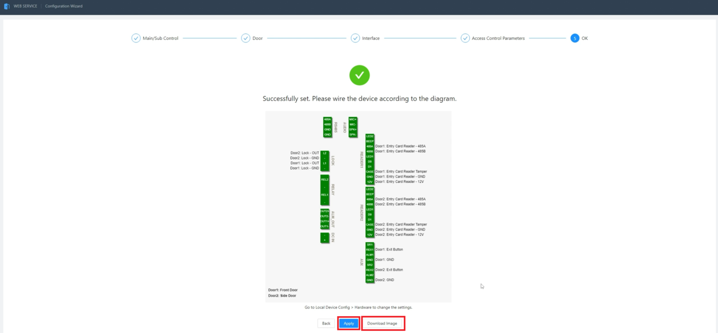
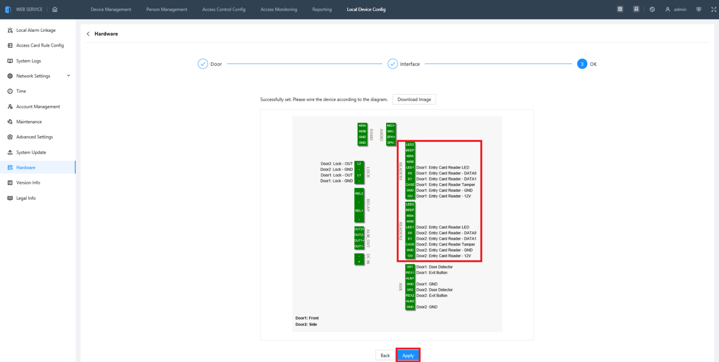
11. This page shows the wiring diagram for you ASC3202B based on the settings you chose in the previous steps.
If you want to download an image of the diagram for reference, click on Download Image.
When you are done, click on Apply
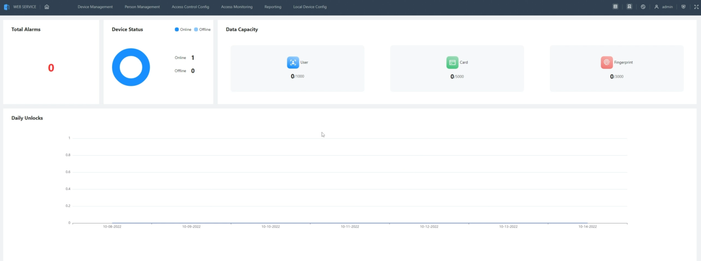
12. Once all the settings are applied, you will see the Statistics page with all the general information about the ASC3202B
Creating New Users and Departments
1. Click on Person Management at the top of the web interface.
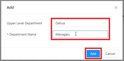
Then click on the + symbol to create a new Department
2. Click on the drop-down next to Upper Level Department to choose which department this new department will fall under.
Then click on Add
3. The new department will show up in the list on the left.
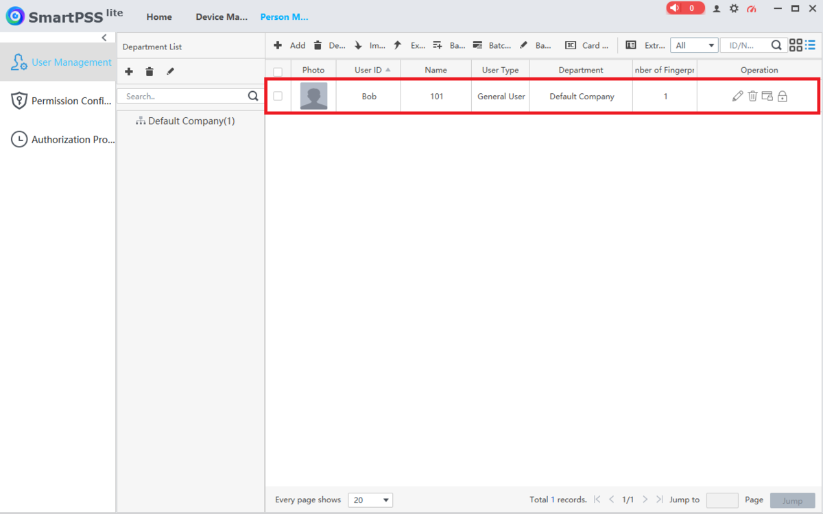
To add a user, select the department you want to add them to from the list, then click on Add
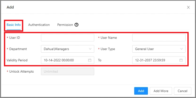
4. Enter a numerical user ID in the field next to User ID, making sure it is unique from any other exiting User ID on the ASC3202B.
Enter the name of the user in the field next to User Name.
Verify the department you are adding the user to in the drop-down next to Department.
Choose what type of user this will be from the drop-down next to User Type.
Verify the Dates and Times the user will have access via the fields next to Validity Period
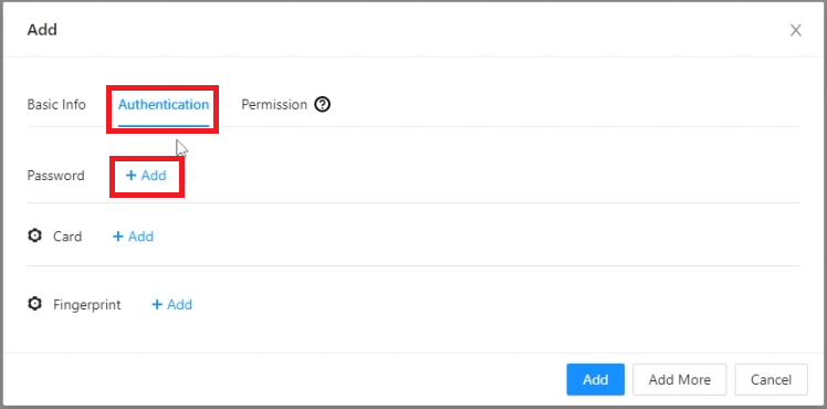
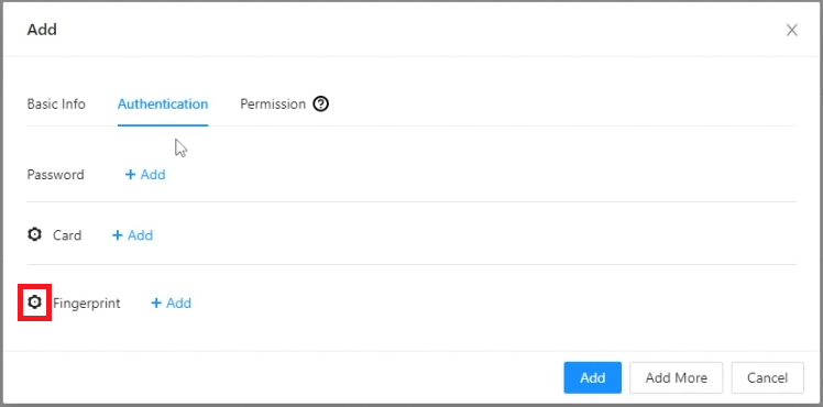
5. Click on Authentication at the top.
To add a PIN password, click on + Add next to Password.
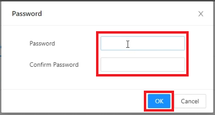
6. Enter the PIN password for the user in the Password and Confirm Password fields.
Then click on OK
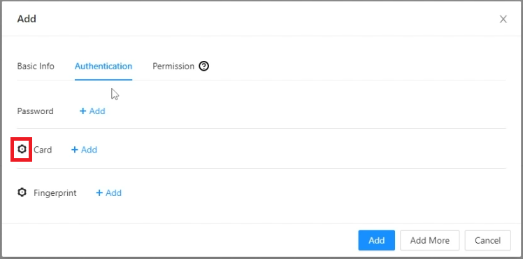
7. To configure the connected device that will capture the card number, first click on the Gear icon to the left of Card
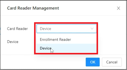
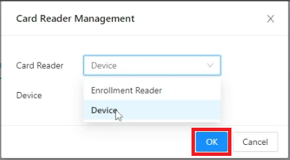
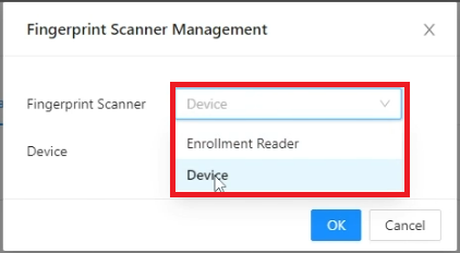
8. Click on the drop-down next to Card Reader and either select Enrollment Reader if you are using a USB card enrollment device connected to your computer, or Device if you are using a card reader that is already wired to the ASC3202B
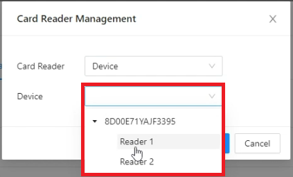
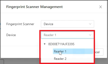
9. If you selected Device in the previous step, click on the drop-down next to Device and select which reader you plan to use to scan in the card for this user.
10. Click on OK at the bottom
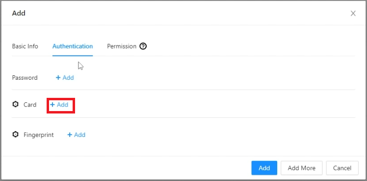
11. Click on + Add next to Card
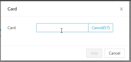
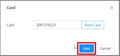
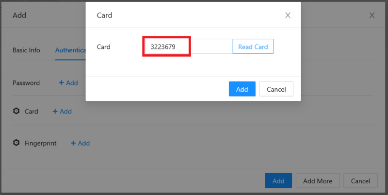
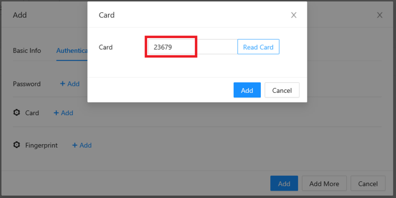
12. While the timer counts down on the right, scan the card on the physical reader connected to the connections on the ASC3202B associated with your selection from Step 9 above
13. Once the card number appears in the field, click on Add
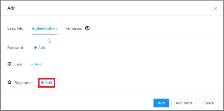
14. To configure the connected device that will capture a fingerprint, first click on the Gear icon to the left of Fingerprint
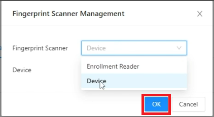
15. Click on the drop-down next to Fingerprint Scanner and either select Enrollment Reader if you are using a USB fingerprint enrollment device connected to your computer, or Device if you are using a fingerprint reader that is already wired to the ASC3202B
16. If you selected Device in the previous step, click on the drop-down next to Device and select which reader you plan to use to scan the fingerprint for this user.
17. Click OK at the bottom
18. Click on + Add next to Fingerprint
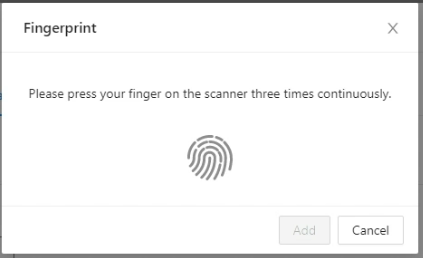
19. Have the user press their finger to the fingerprint scanner connected to the connections on the ASC3202B associated with your selection from Step 16 above.
Have the user lift up their finger and press it back down 3 times
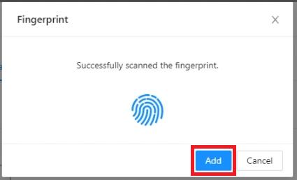
20. Once the user has scanned their fingerprint enough times successfully, it will show Successfully scanned the fingerprint.
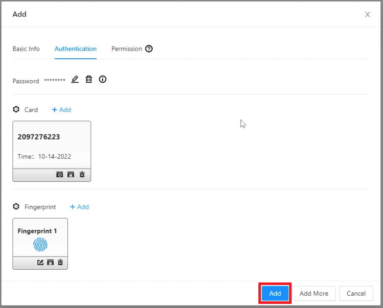
Click on Add at the bottom
21. When you have added all cards, fingerprints, and the password that you want for this user, click on Add
22. Now that the user has been added, you will see them in the list
Configuring User Permissions
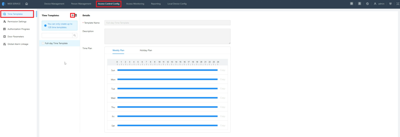
1. Click on Access Control Config at the top of the web interface.
Select Time Template on the left.
Then click on the + symbol to create a new Time Template
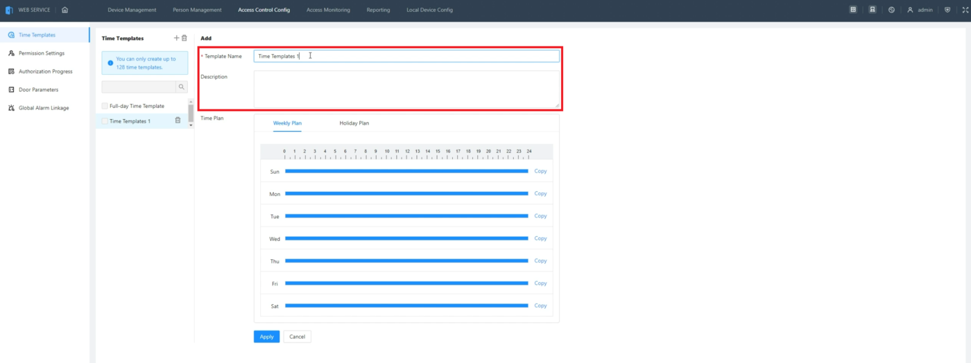
2. Enter a name for the Time Template you are creating in the field next to Template Name.
Optionally, put in any other extra information in the Description field
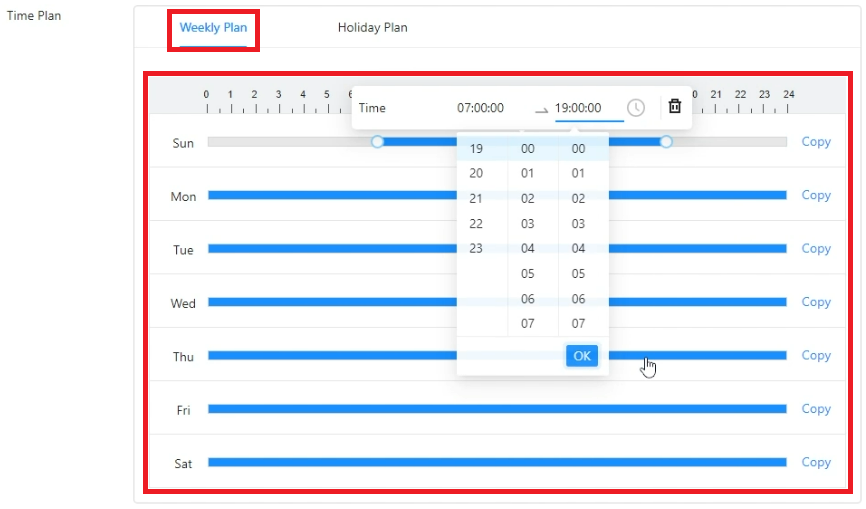
3. Select Weekly Plan at the top of the Time Plan section.
Then use the sliders or choose from the drop-downs to adjust the start and end time for the schedule for each day of the week
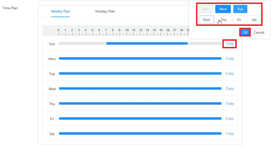
4. If you want to copy the time settings from one day to another, click on Copy to the right of that day and then select the days of the week to copy it to.
Then click on OK to push those changes to those days
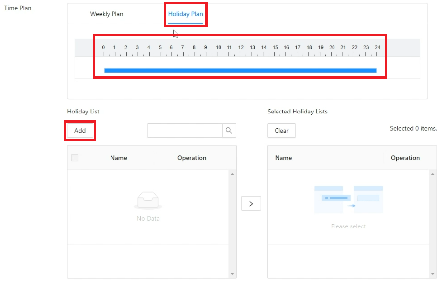
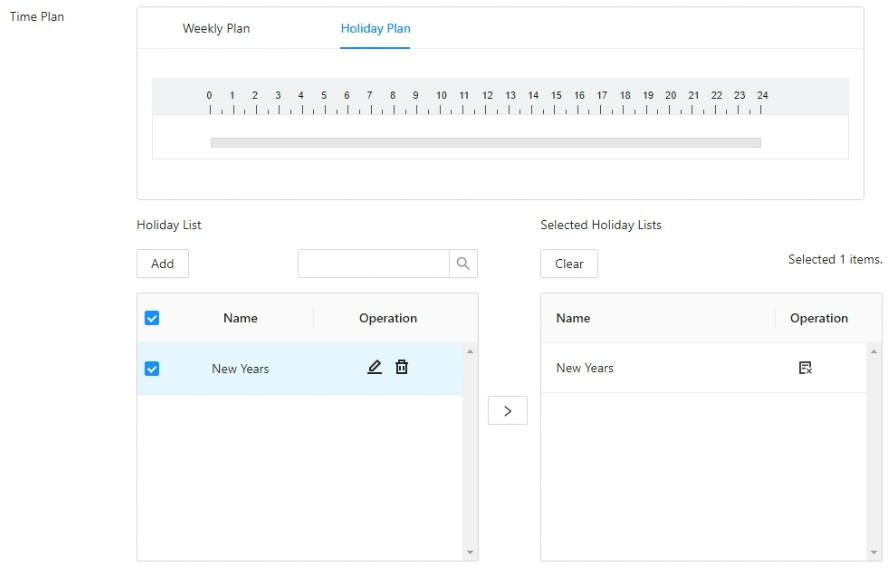
5. To set the Holiday schedule for this time template, click on Holiday Plan at the top of the Time Plan section.
Then adjust the access schedule for holidays. (If you don’t want anyone to have access during holidays, you can clear out the holiday schedule.)
Select Add below Holiday List to add a specific day as a holiday
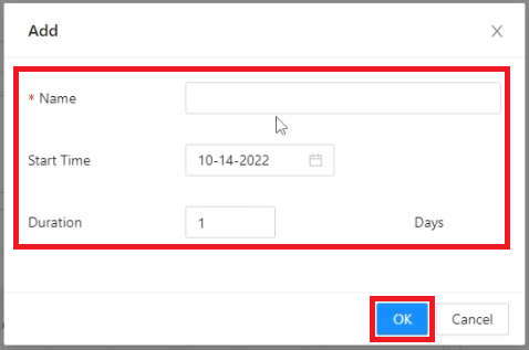
6. Enter the name of this holiday in the field next to Name.
Select the drop-down next to Start Time and set it to the day this holiday will start.
Then enter a number in the field next to Duration for how many days the holiday will last.
Click on OK at the bottom
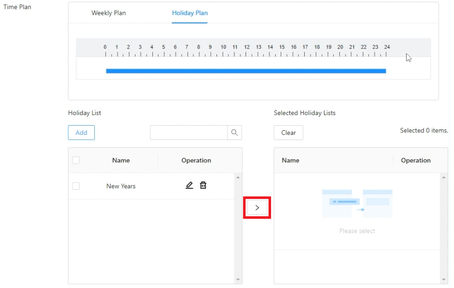
7. The holiday you just created will appear in the list on the left.
You can repeat the process from Steps 5-6 above for more holidays.
Once you have all the holidays you want in the list on the left, click on the > button to make them active on this Time Template
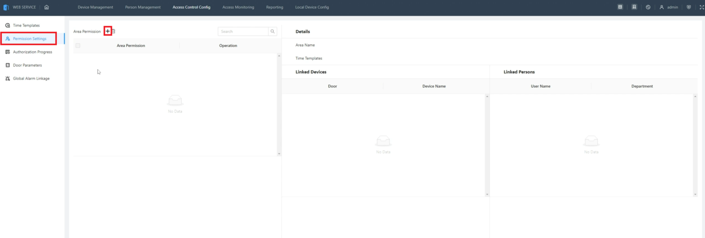
8. Select Permission Settings on the left.
Then click on + next to Area Permission
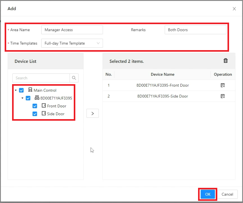
9. Enter the name of the permission group in the field next to Area Name.
Choose a Time Template from the drop-down next to Time Templates.
Add any notes about this permission group in the field next to Remarks.
Then check the boxes next to the doors you want this permission group to have access to.
Click on OK
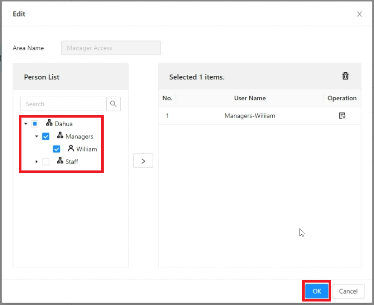
10. Click on the Users icon under Operation for the permission group you just created
11. Check the boxes next to the Users and/or Departments you want to add to this permission group.
Then click on OK to save the changes
Adding ASC3202B to DMSS Mobile App
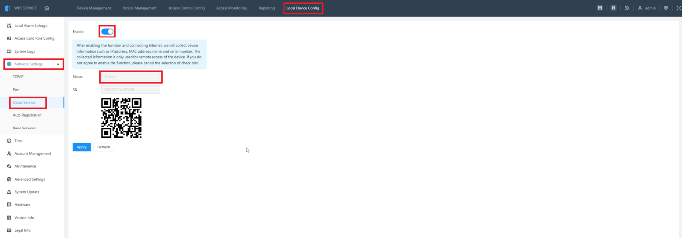
1. Click on Local Device Config at the top of the web interface.
Select Network Settings on the left.
Then select Online Service.
Make sure the slider it set to the ON position next to Enable.
Verify that Status shows Online
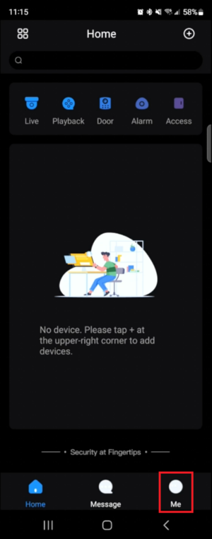
2. In the DMSS app on your mobile device, select Me at the bottom
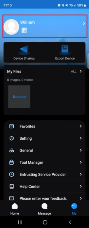
3. Verify you are logged into a DMSS Account.
If you are not, click the Log in button at the top, and either sign into an existing account or create a new one
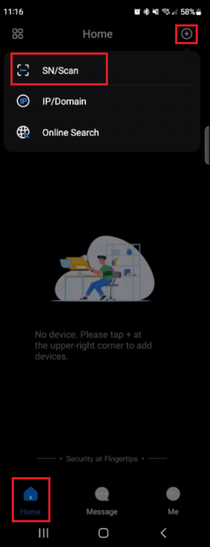
4. Select Home at the bottom.
Select + at the top.
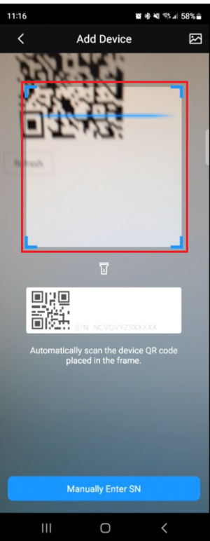
Then select SN/Scan
5. Aim your mobile device’s camera at the QR code on your screen from Step 1
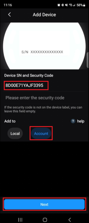
6. Once the QR code has been successfully scanned, you will see the ASC3202B’s serial number on your mobile device’s screen.
Make sure that Account is selected under Add to.
Select Next at the bottom
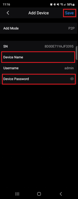
7. Enter the name you want to identify your ASC3202B by in the field next to Device Name.
Enter the ASC3202B’s password in the field next to Device Password.
Select Save at the top
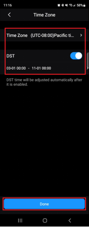
8. Verify the Time Zone and Daylight Savings settings are set correctly for your location.
Then select Done at to bottom
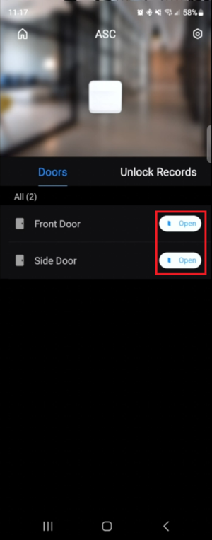
9. You will now see the door information for your ASC3202B.
You can manually open either door by selecting Open to the right of the name of the door
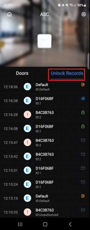
10. Select Unlock Records to see the unlock history for your ASC3202B
How To Setup Holiday Schedule On DHI-ASC3202B
Description
This article will cover how to setup a Holiday Schedule on a DHI-ASC3202B
Prerequisites
- Initialized DHI-ASC3202B
- A Computer connected to the DHI-ASC3202B
Video Instructions
Coming Soon
Step by Step Instructions
1. Log into the web interface of the ASC3202B and click on Access Control Config at the top.
Select Time Template on the left.
Then click on the + symbol to create a new Time Template
2. Enter a name for the Time Template you are creating in the field next to Template Name.
Optionally, put in any other extra information in the Description field
3. Select Weekly Plan at the top of the Time Plan section.
Then use the sliders or choose from the drop-downs to adjust the start and end time for the schedule for each day of the week
4. If you want to copy the time settings from one day to another, click on Copy to the right of that day and then select the days of the week to copy it to.
Then click on OK to push those changes to those days
5. To set the Holiday schedule for this time template, click on Holiday Plan at the top of the Time Plan section.
Then adjust the access schedule for holidays. (If you don’t want anyone to have access during holidays, you can clear out the holiday schedule.)
Select Add below Holiday List to add a specific day as a holiday
6. Enter the name of this holiday in the field next to Name.
Select the drop-down next to Start Time and set it to the day this holiday will start.
Then enter a number in the field next to Duration for how many days the holiday will last.
Click on OK at the bottom
7. The holiday you just created will appear in the list on the left.
You can repeat the process from Steps 5-6 above for more holidays.
Once you have all the holidays you want in the list on the left, click on the > button to make them active on this Time Template
8. After setting up the Holiday schedule, you can apply the time template to a door group and when the holiday occurs, it will overwrite the regular schedule for those doors and users.
How To Setup Heat Alarms On DHI-ASC3202B
Description
This article will cover how to setup Heat Alarms on a DHI-ASC3202B
Prerequisites
- Initialized DHI-ASC3202B
- A Computer connected to the DHI-ASC3202B
- A 3rd Party Fire Detection Device
Video Instructions
Coming Soon
Step by Step Instructions
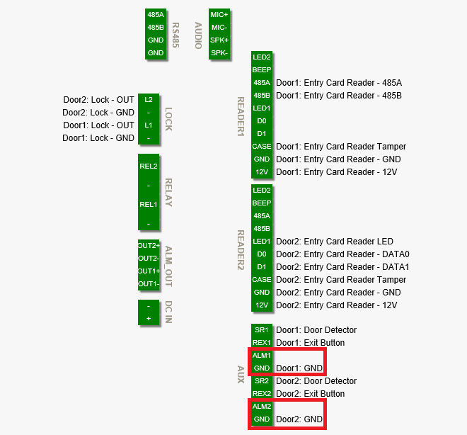
1. Wire the 3rd Party Heat Detection Device to Alarm Input 1 or Alarm Input 2 on the ASC3202B
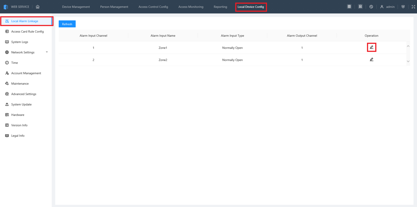
2. Log into the web interface of the ASC3202B and click on Local Device Config at the top.
Select Local Alarm Linkage on the left.
Then click on the Edit Button to the right of the Alarm Input Channel associated with the connection you made in Step 1 above
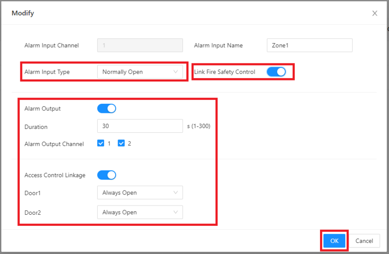
3. Enable the toggle next to Link Safety Control.
Change the setting next to Alarm Input Type for the type of input the Heat Detection Device uses, either Normally Open or Normally Closed.
Change all the settings below for what will happen if extreme heat is detected:
- Alarm Output: Trigger the alarm output wired to the ASC3202B
- Duration: How long the alarm output will be triggered (in seconds)
- Alarm Output Channel: Which alarm output channel(s) will be triggered
- Access Control Linkage: Set if the door(s) are Always Open or Always Closed when the alarm is triggered
- “Door1” & “Door2”: Which state will be enabled for that door when the alarm is triggered (If you changed the names of the doors during the intial setup, these will have the names of those doors)
Click on “OK” at the bottom
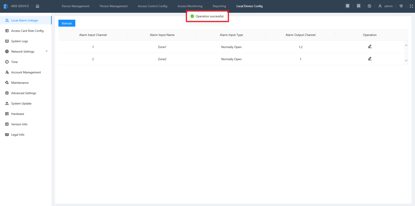
4. Once the changes are saved you will see “Operation successful.” at the top.
Repeat this process for the other alarm input, if needed
How To Use HID Cards On DHI ASC3202B
Description
This article will cover how to setup a DHI-ASC3202B for use with HID Readers and Cards
Prerequisites
- Initialized DHI-ASC3202B
- A Computer connected to the DHI-ASC3202B
- HID Card Reader
- HID Cards
Video Instructions
Coming Soon
Step by Step Instructions
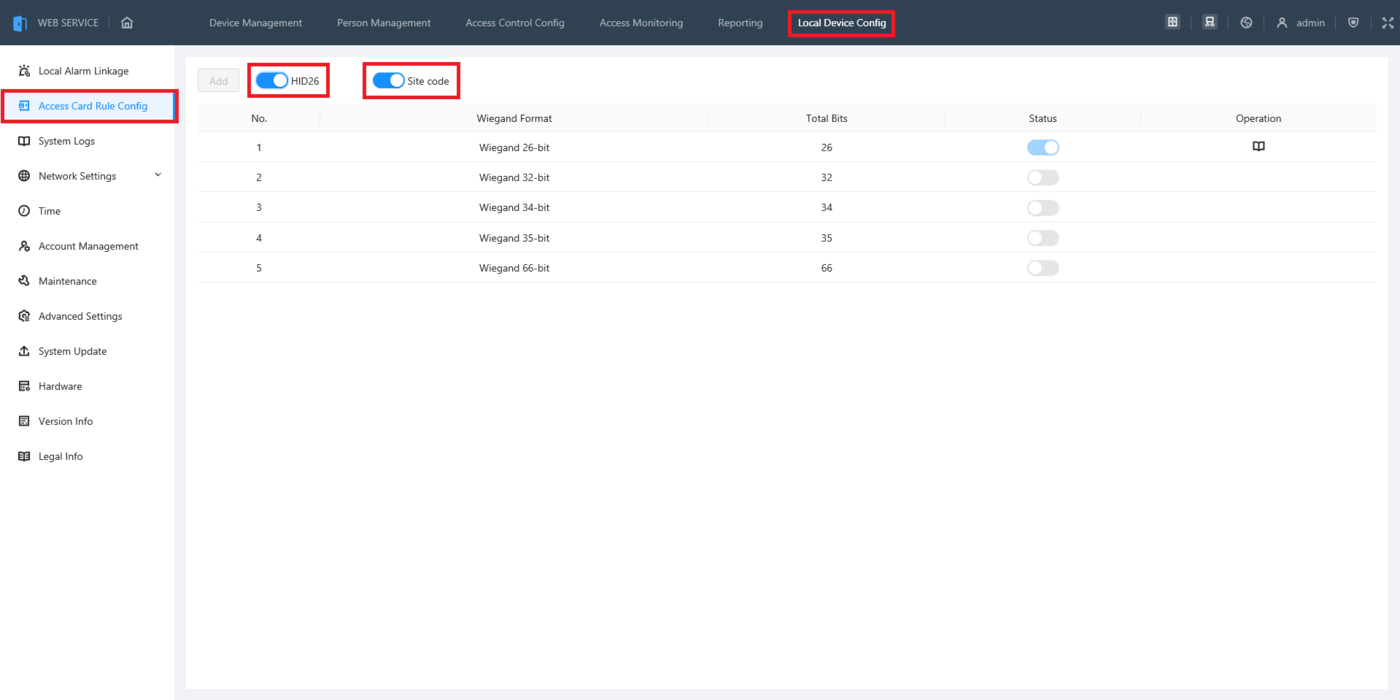
1. Log into the web interface of the ASC3202B and click on Local Device Config at the top.
Then select Access Card Rule Config on the left.
Enable the slider next to HID26 so HID readers and cards can be used.
Either enable Site Code to have the HID card numbers registered in the controller with the site code included,
or disable the slider to have the HID card numbers registered in the controller with the site code excluded (See Step 6 below for more information)
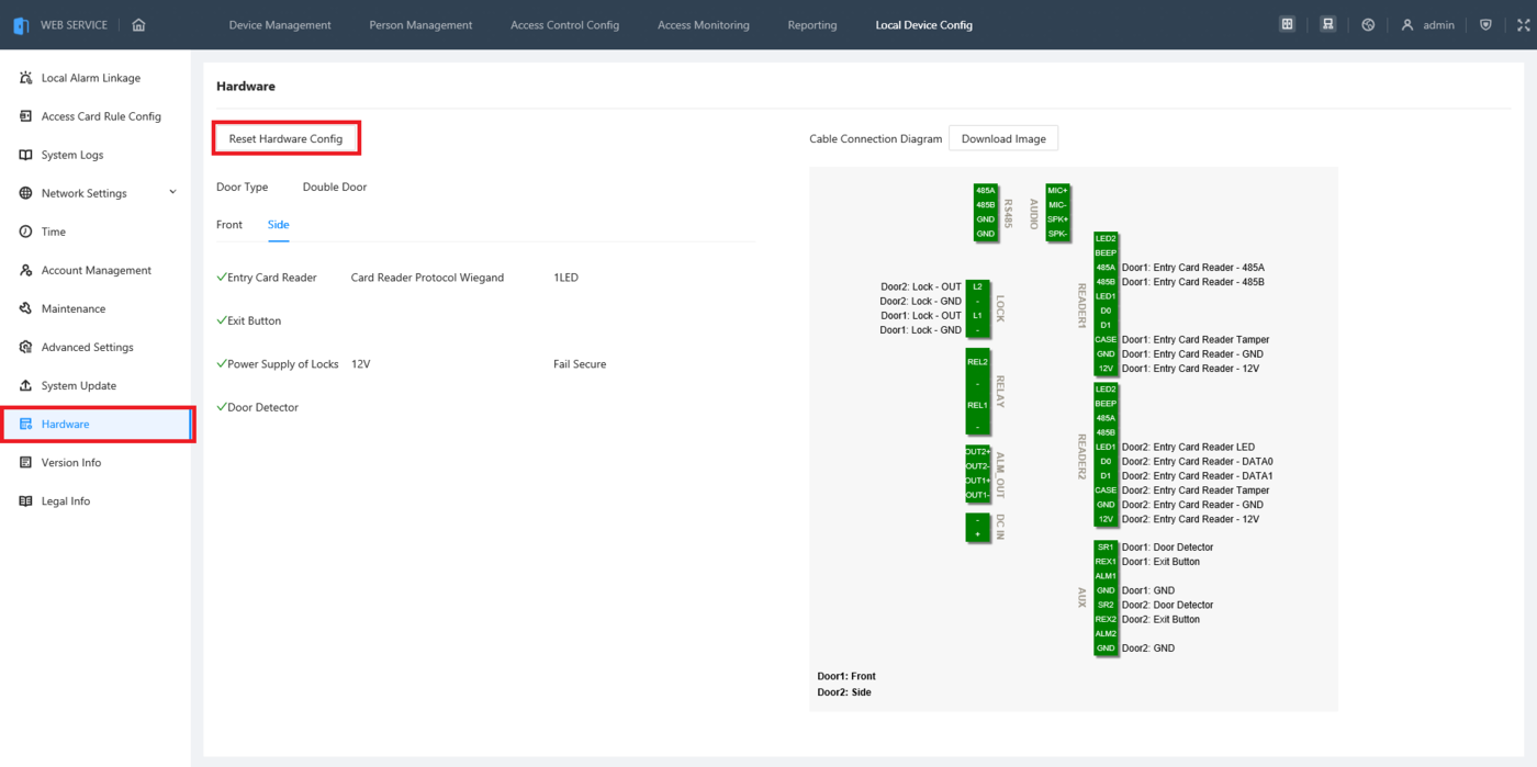
2. If you have not already configured the ASC3202B to work with Wiegand readers, select Hardware on the left. (If you have already, you can skip to Step 6)
Then select Reset Hardware Config
3. If you plan to use this as a single door access controller, select Single Door.
If you plan to use this as a 2 door access controller, select Double Door.
Type in the name(s) of the door(s) in the field(s) to the right.
Then click on Next
4. Check the boxes next to Entry Card Reader for each door.
Then enable the option for Wiegand.
Click on Next
5. Use the diagram on this screen to guide you in wiring the HID card reader to the ASC3202B.
When you are done looking at the diagram, click on Apply
6. Follow the guide on “Creating New Users and Departments” from the page on How to Setup a DHI-ASC3202B
When you get to the part where you scan in a card, scan the HID card on the HID reader you connected to the ASC3202B.
If you enabled the setting for “Site Code” in Step 1, you will see the site code as part of the card number:
If you disabled the setting for “Site Code” in Step 1, you will see just the card number without a site code:
How To Batch Import And Export Users And Cards On DHI-ASC3202B
Description
This article will cover how to batch Import and Export Users and Cards on a DHI-ASC3202B
Prerequisites
- Initialized DHI-ASC3202B
- A Computer connected to the DHI-ASC3202B
- Microsoft Excel
Video Instructions
Coming Soon
Step by Step Instructions
Export Users and Cards
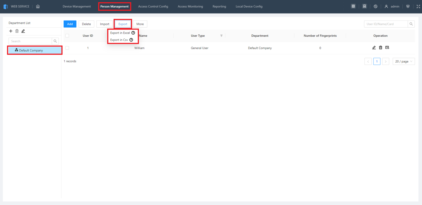
1. To export existing users, log into the web interface of the ASC3202B and click on Person Management at the top.
Then select the department of users you want to work with on the left.
Click on Export at the top.
Then either select Export to Excel to export it as an xlsx file or select Export in Csv to export it as a CSV file
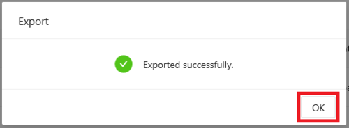
2. Once the export has completed successfully you will see a message of “Exported successfully.”
Click on OK
Import Users and Cards
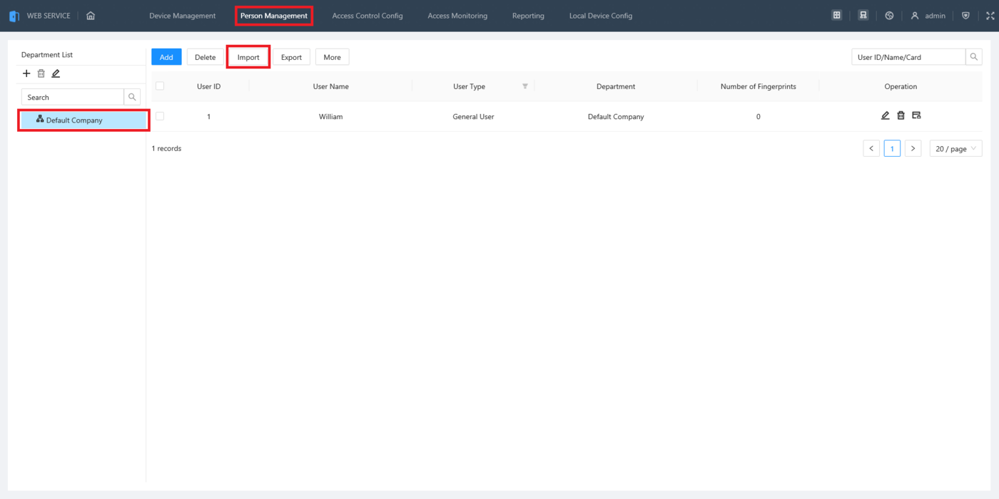
1. Log into the web interface of the ASC3202B and click on Person Management at the top.
Then select the department of users you want to work with on the left.
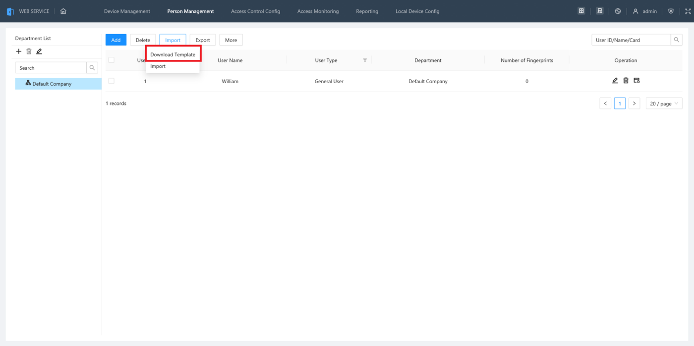
Click on Import at the top
2. If you want to manually enter user information and card numbers, select Download Template.
If want to import existing users from an exported file, skip to Step 4
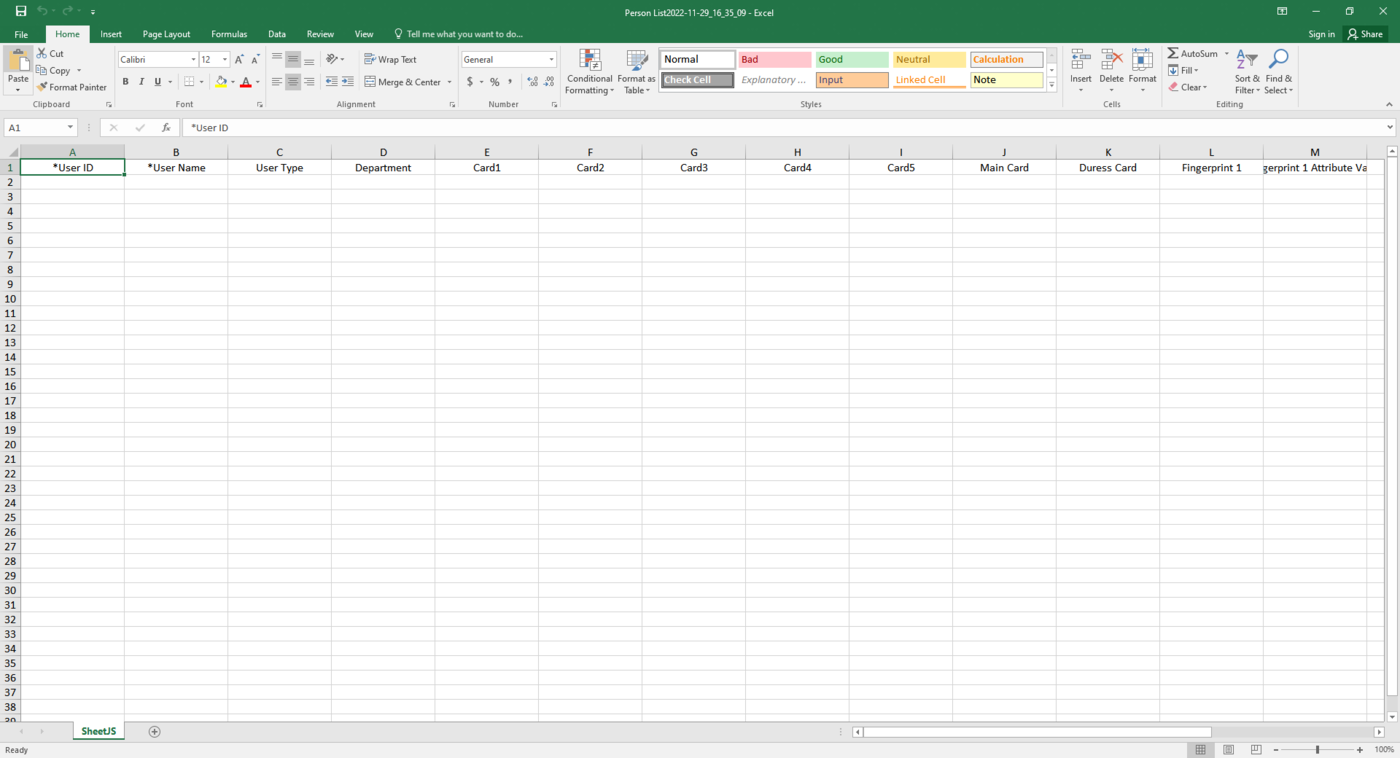
3. Open the file you downloaded in Excel.
Fill in the information for each user on each line (Columns with an asterisk * are required. The rest are optional.)
When done inputting information, save the document
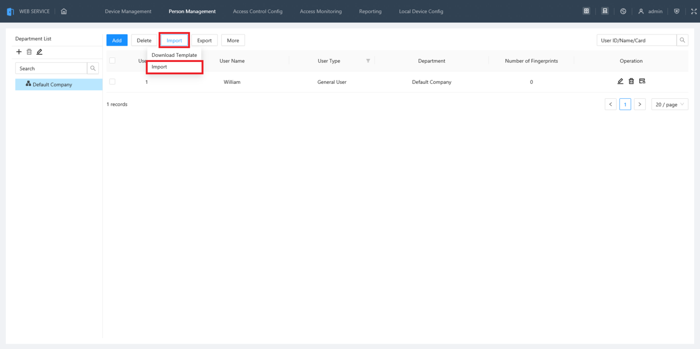
4. Back in the web interface of the ASC3202B click on Import.
Then click on Import in the drop-down
5. Search your file system for the excel document you filled out in the previous steps or had previously exported.
Select it and then click on Open
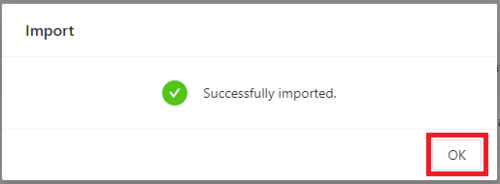
6. Once the import has completed successfully you will see a message of “Successfully imported.”
Click on OK
How To Setup Holiday Schedule in SmartPSS Lite
Description
This article will cover how to setup a Holiday Schedule for Access Control on SmartPSS Lite
Prerequisites
- Any 2nd Generation Dahua Access Controller
- A Computer with SmartPSS Lite
- Access Control Initial Setup
Video Instructions
Coming Soon
Step by Step Instructions
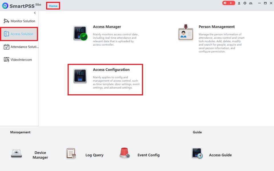
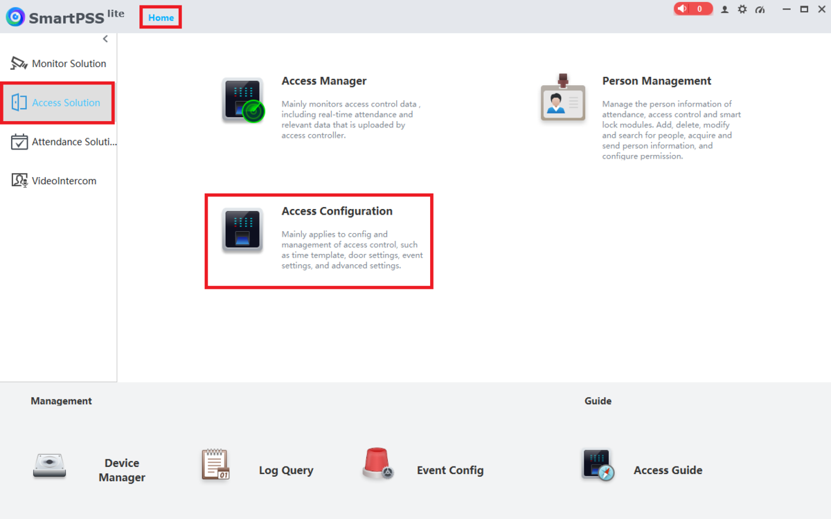
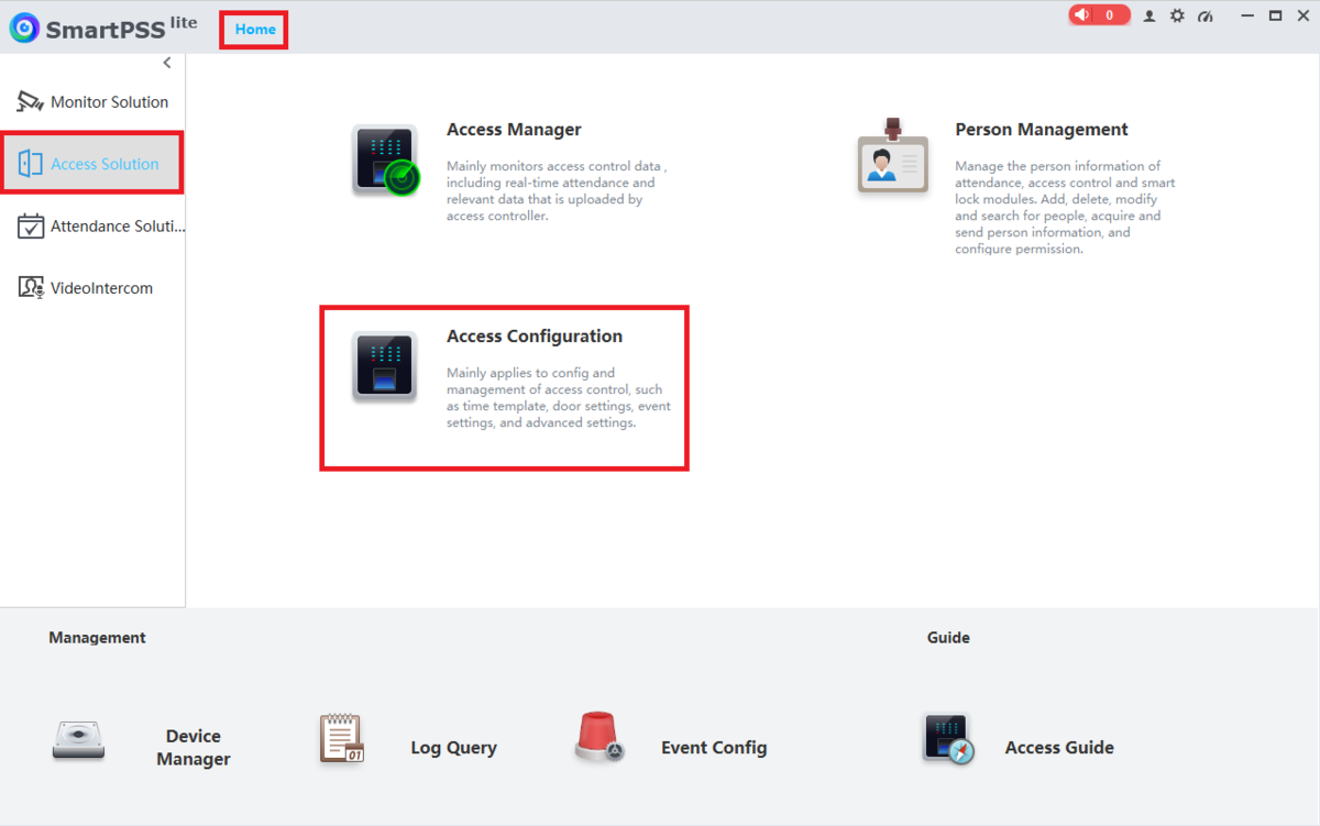
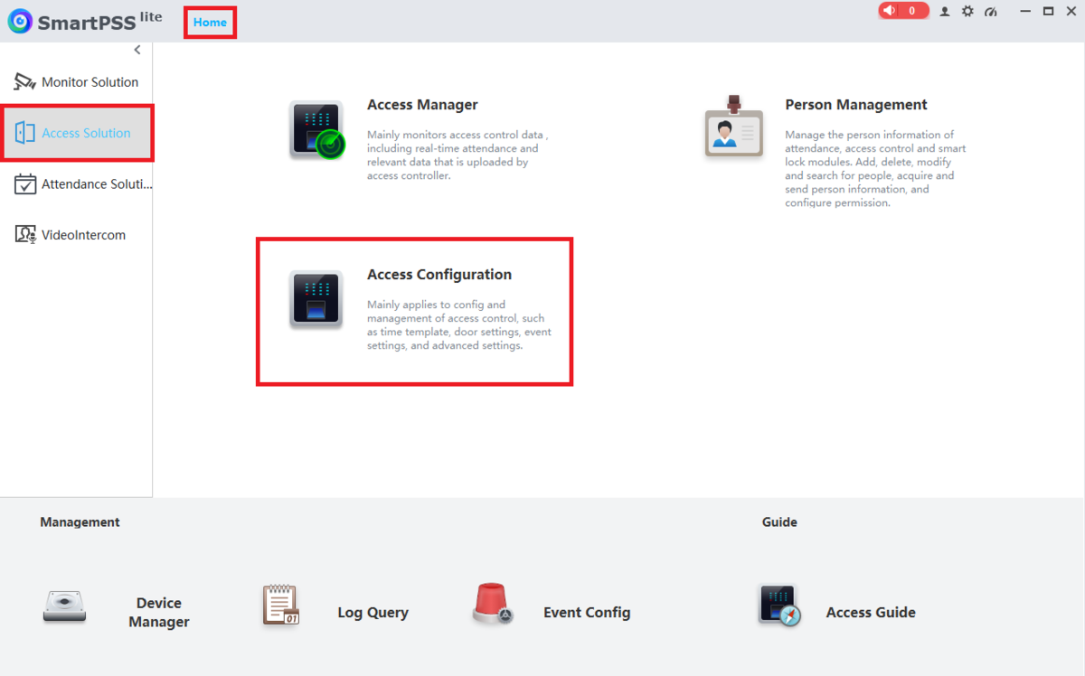
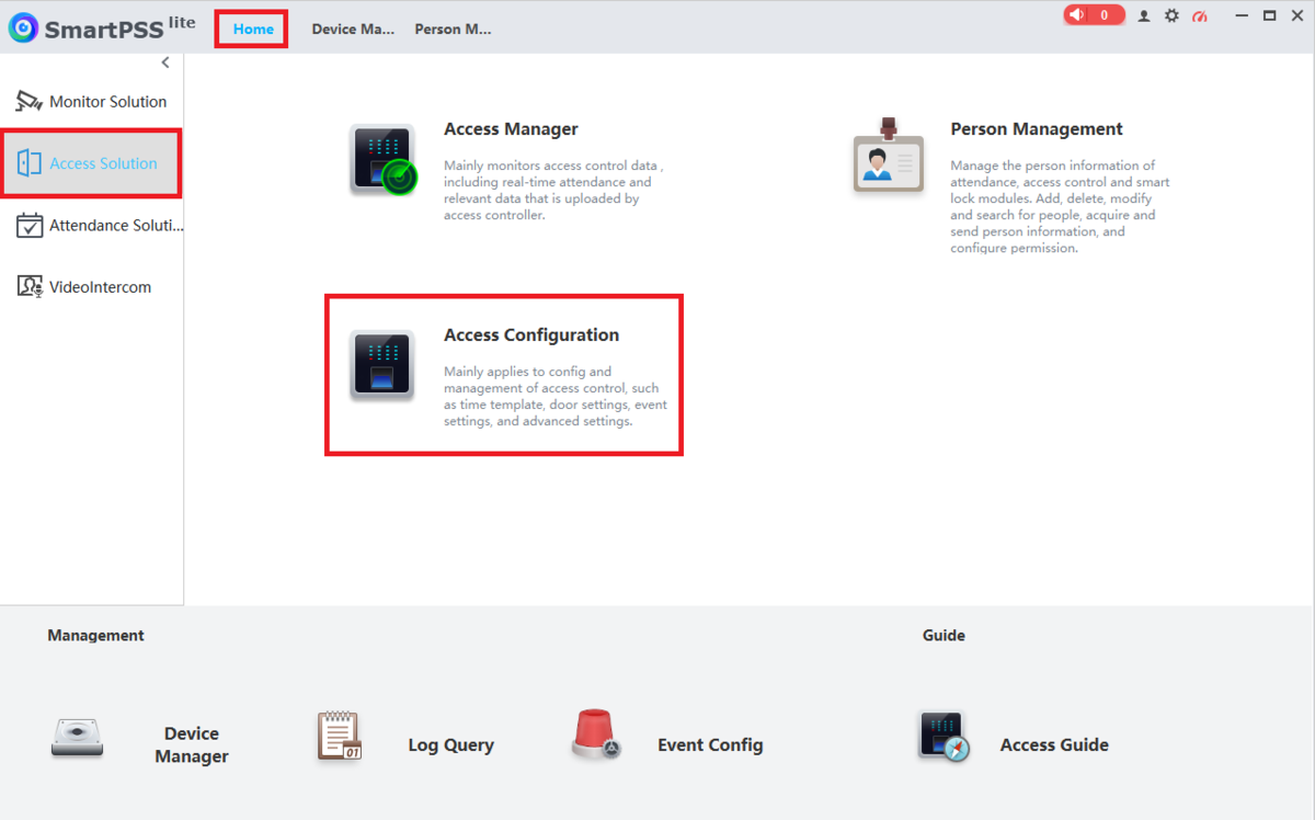
1. Open SmartPSS Lite.
Click on Home at the top.
Click on Access Solution on the left.
Then click on Access Configuration
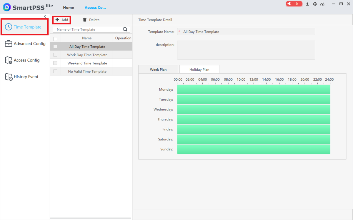
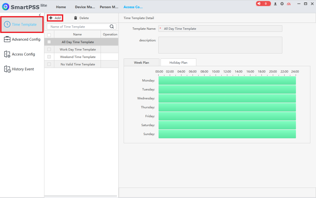
2. Select Time Template on the left.
Then select + Add at the top ot create a new Time Template
3. Enter a name for the Time Template you are creating in the Template Name field.
Optionally, put in any other extra information in the Description field.
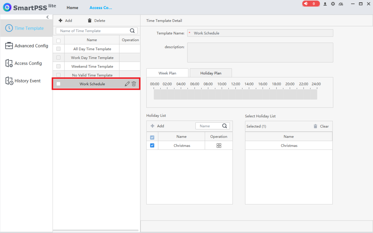
Select the Week Plan tab and then modify the schedule for each day of the week below.
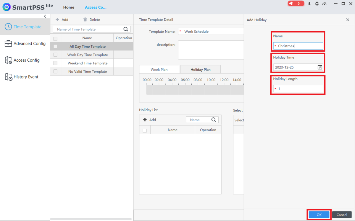
4. Select the Holiday Plan tab.
Then adjust the access schedule for holidays. (If you don’t want anyone to have access during holidays, you can clear out the holiday schedule.)
Select + Add below “Holiday List” to add a specific day as a holiday
5. Enter the name of this holiday in the Name field.
Click on the calendar icon in the Holiday Time field and set it to the day this holiday will start.
Then enter a number in the Holiday Length field for how many days the holiday will last.
Click on OK at the bottom
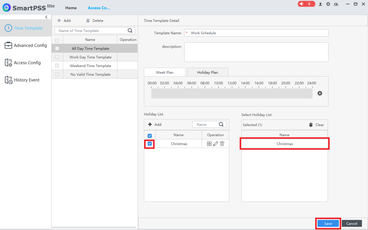
6. The holiday you just created will appear in the “Holiday List” on the left.
You can repeat the process from Steps 4-5 above for more holidays.
Once you have all the holidays you want in the list on the left, check the boxes next each holiday to make them active on this Time Template.
Select Save at the bottom
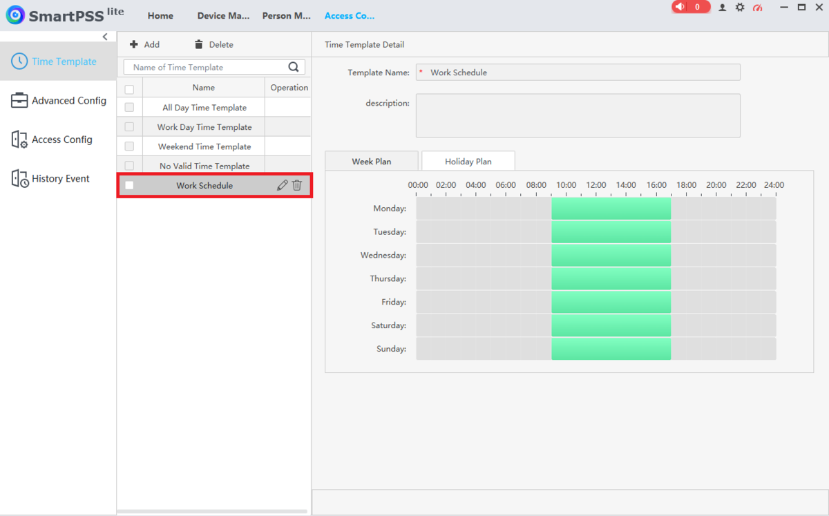
7. You will now see the Time Template you just created (which includes the Holiday Schdule) in the list on the left
How To Setup Multi-Card Unlock in SmartPSS Lite
Description
This article will cover how to setup Multi-card Unlock for Access Control on SmartPSS Lite
Prerequisites
- Any 2nd Generation Dahua Access Controller
- A Computer with SmartPSS Lite
- Access Control Initial Setup
Video Instructions
Coming Soon
Step by Step Instructions
1. Open SmartPSS Lite.
Click on Home at the top.
Click on Access Solution on the left.
Then click on Access Configuration
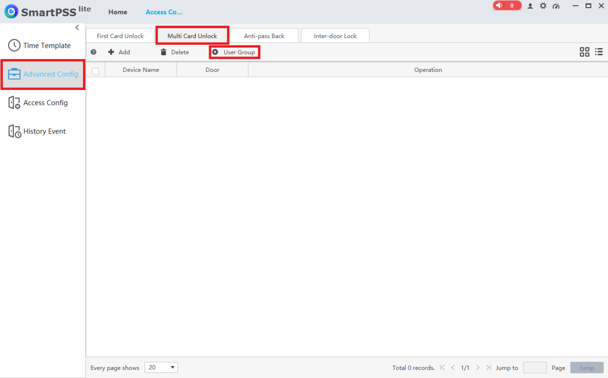
2. Click on Advanced Config on the left.
Click on the Multi-Card Unlock tab at the top.
Then click on User Group at the top
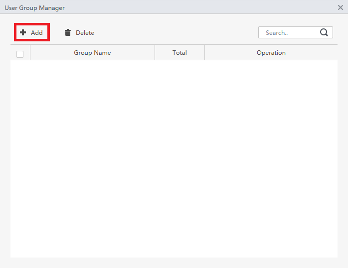
3. Click on + Add
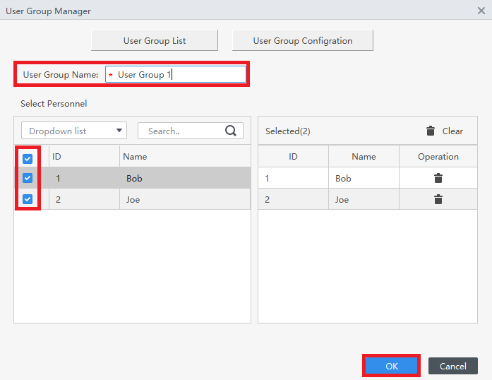
4. Enter the name of this User Group in the User Group Name field.
Check the boxes on the left next to the users you want to add to this group.
Click on OK
5. You will see the added User Group in the list.
Click the X at the top right to close this window
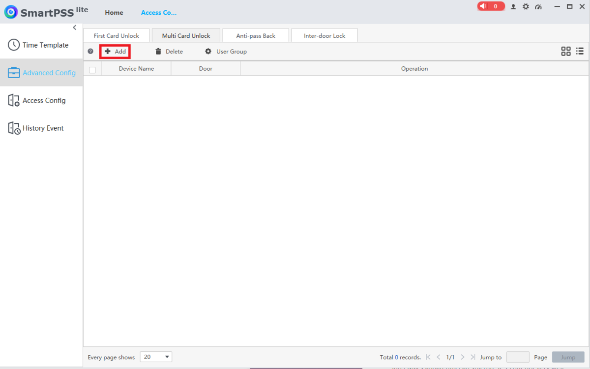
6. Click on + Add at the top
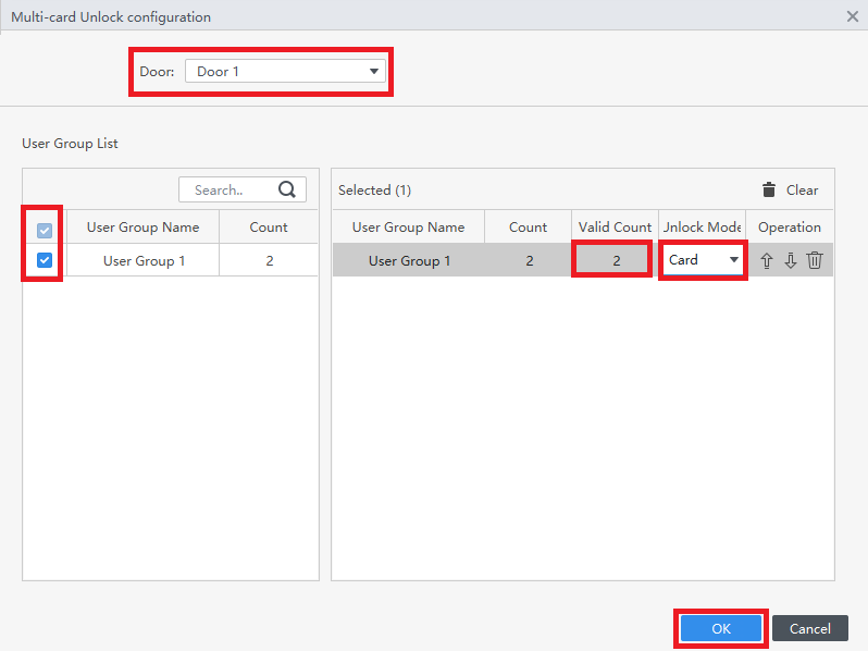
7. Select which door this rule will be applied to via the Door drop-down.
Check the box next to the user group.
Double-click on the field below Valid Count and enter the number of users from the User Group required to authenticate to open this door.
Click the drop-down below Unlock Mode and choose which authentication method is requires: Card, Password, or Fingerprint.
Click on OK at the bottom
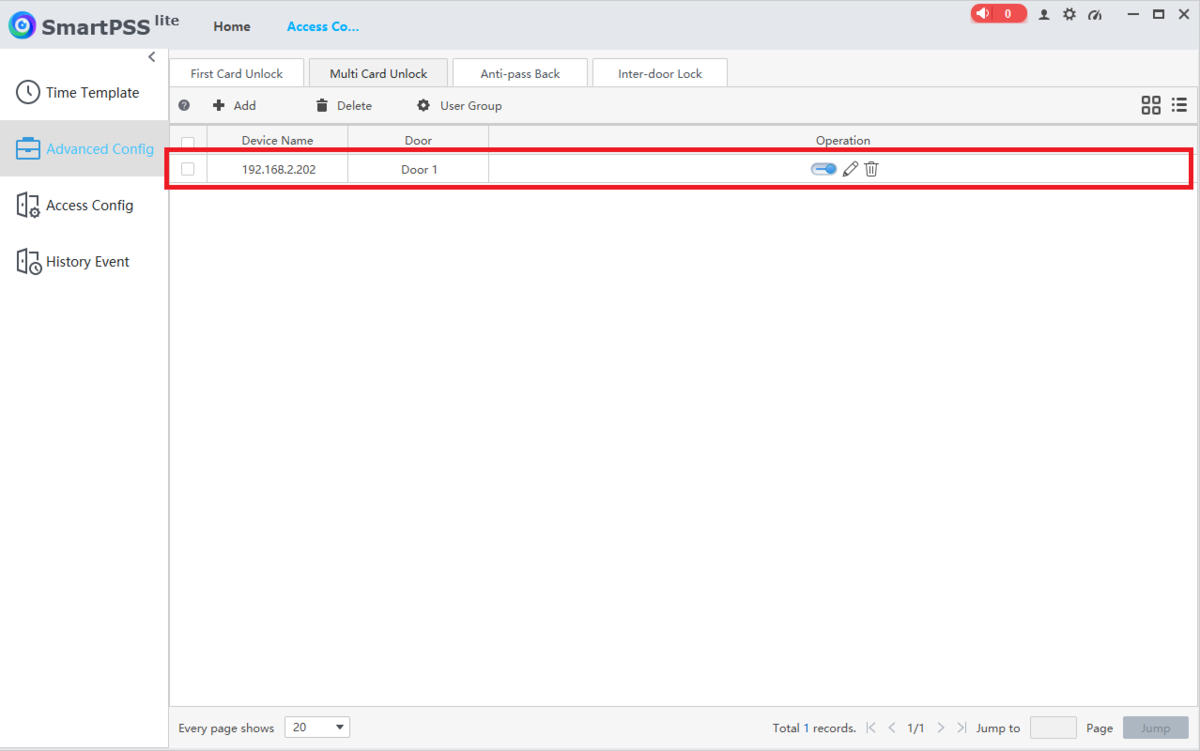
8. You will see the saved Multi-Card Unlock rule in the list.
The chosen door will now require the number of “Valid Count” users from the User Group to authenticate before that door will unlock
How To Setup Anti-Passback in SmartPSS Lite
Description
This article will cover how to setup Anti-Passback for Access Control on SmartPSS Lite
Prerequisites
- Any 2nd Generation Dahua Access Controller
- A Computer with SmartPSS Lite Installed
- Access Control Initial Setup
Video Instructions
Coming Soon
Step by Step Instructions
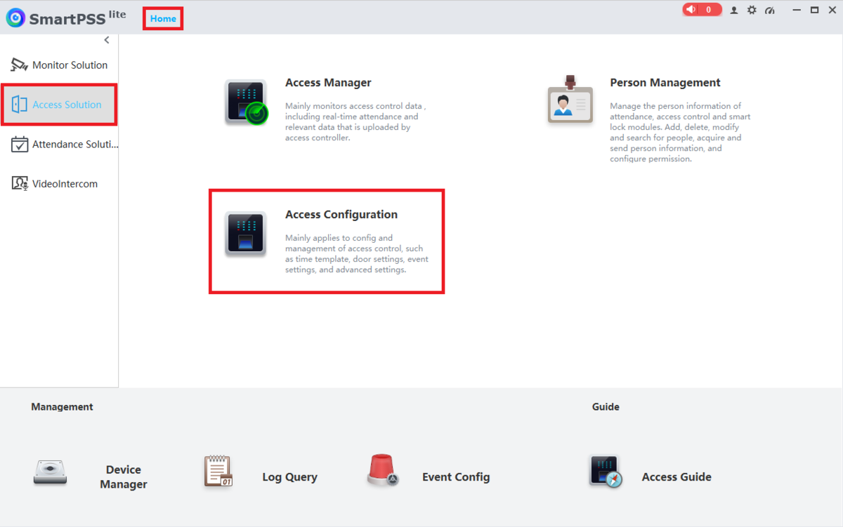
1. Open SmartPSS Lite.
Click on Home at the top.
Click on Access Solution on the left.
Then click on Access Configuration
2. Click on Advanced Config on the left.
Click on the Anti-passback tab at the top.
Then click on + Add at the top
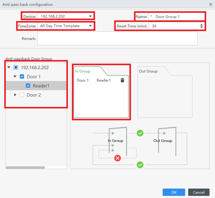
3. Select the access controller from the drop-down list next to Device.
Enter a name for this Anti-Passback rule set in the Name field.
Choose the Time Template from the drop-down list next to TimeZone.
Select an amount of time (in minutes) for the doors to follow the Anti-Passback rule before resetting in the Reset Time (min) field.
Click on the In Group box to highlight it.
Then check the box(es) next to the door(s) you want added to the entry group.
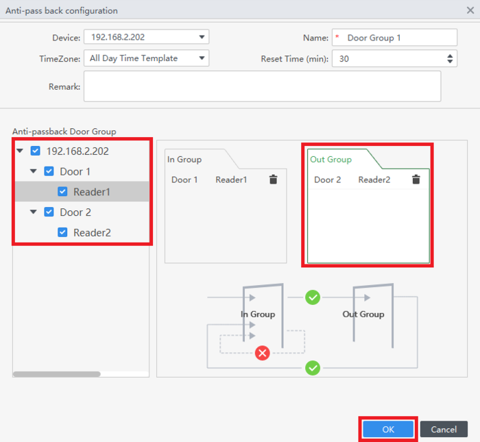
4.Click on the Out Group box to highlight it.
Check the box(es) next to the door(s) you want added to the exit group.
Then click OK at the bottom
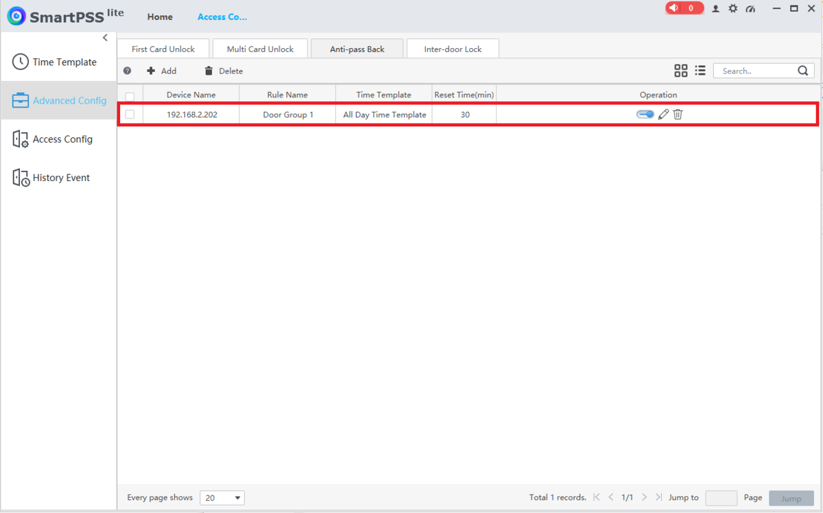
5. You will see the saved Anti-Passback rule in the list.
While it is enabled, all cards must be scanned on the reader on one of the entry doors first to unlock that door and won’t be able to unlock that same door again until they scan their card on the reader on one of the exit doors
How To Setup First Card Unlock in SmartPSS Lite
Description
This article will cover how to setup First Card Unlock for Access Control on SmartPSS Lite
Prerequisites
- Any 2nd Generation Dahua Access Controller
- A Computer with SmartPSS Lite Installed
- Access Control Initial Setup (Including Creating Users and Configuring User Permissions)
Video Instructions
Coming Soon
Step by Step Instructions
1. Open SmartPSS Lite.
Click on Home at the top.
Click on Access Solution on the left.
Then click on Access Configuration
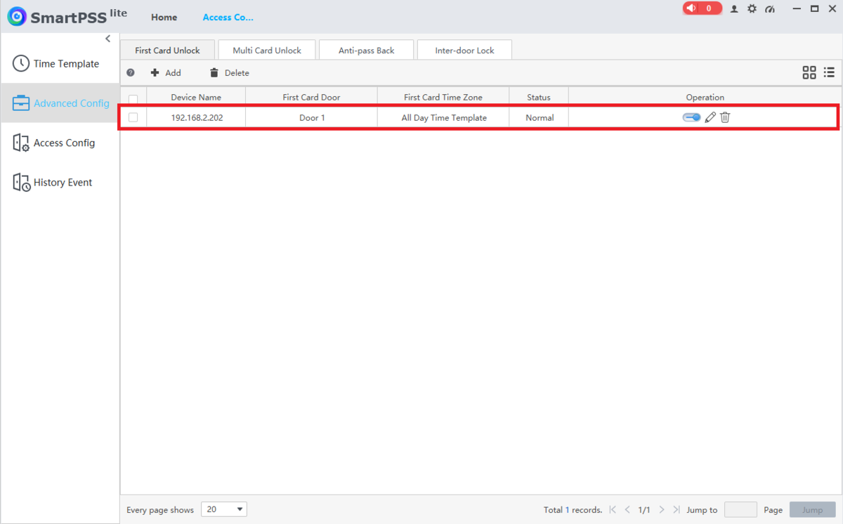
2. Click on Advanced Config on the left.
Click on the First Card Unlock tab at the top.
Then click on + Add at the top
3. Click on the drop-down list next to Door and select the door you want to apply this rule to.
Click on the drop-down list next to Status and select either Normal to have the door stay locked until a valid card is presented after the first card unlock card is swipped, or select Always Open to have the door stay up after the first card unlock card is swiped.
Click on the drop-down list next to Timezone and select the Timezone schedule you want this rule to follow.
Then check the box(es) next to the users you want to allow to be the first card unlock user(s).
And click on Save at the bottom
4. You will now see the rule in the list.
Now the door will remain locked to all users until one of the first card unlock users swipes their card.
How To Setup DHI ASC3202B in SmartPSS Lite
Description
This article will cover how to setup a DHI-ASC3202B in SmartPSS Lite
Prerequisites
- DHI-ASC3202B
- A Computer connected to the DHI-ASC3202B
- SmartPSS Lite
Video Instructions
Coming Soon
Step by Step Instructions
Initialization
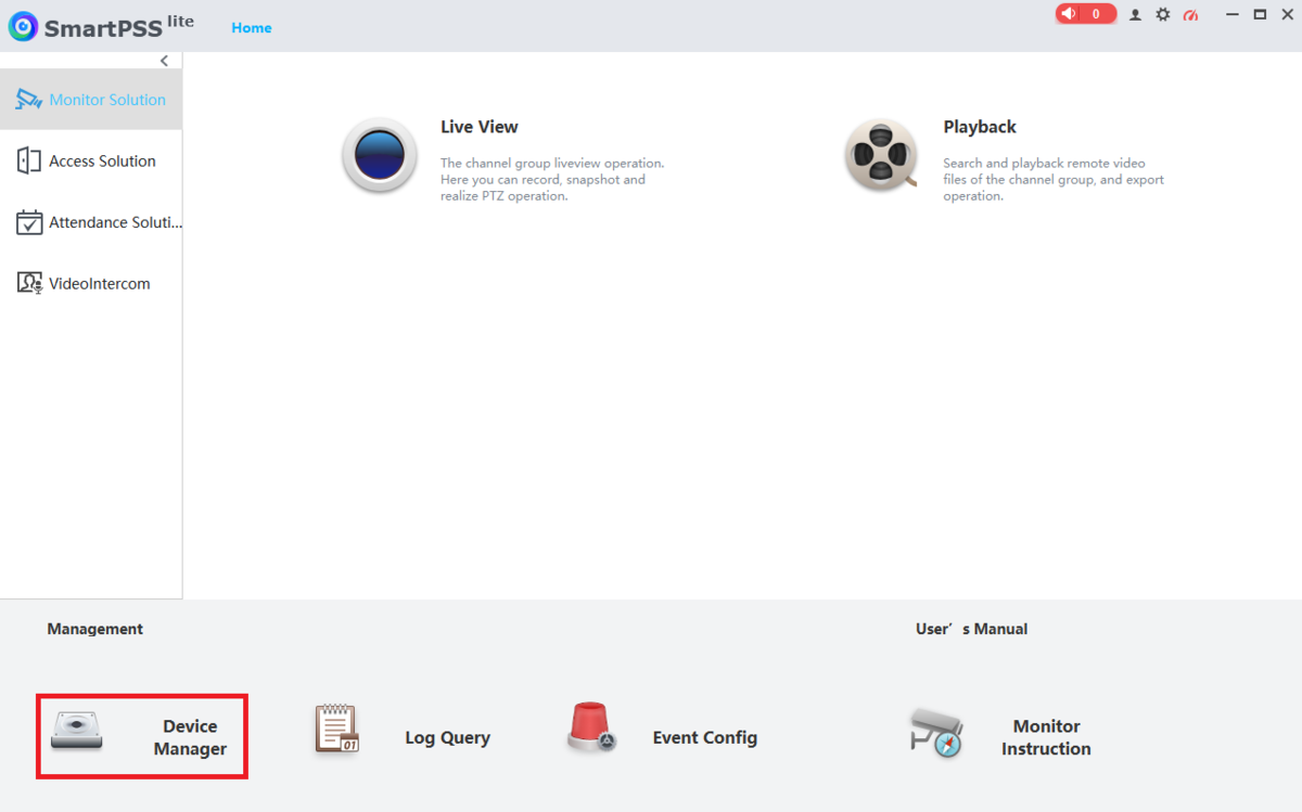
1. Open SmartPSS Lite
Select Device Manager at the bottom
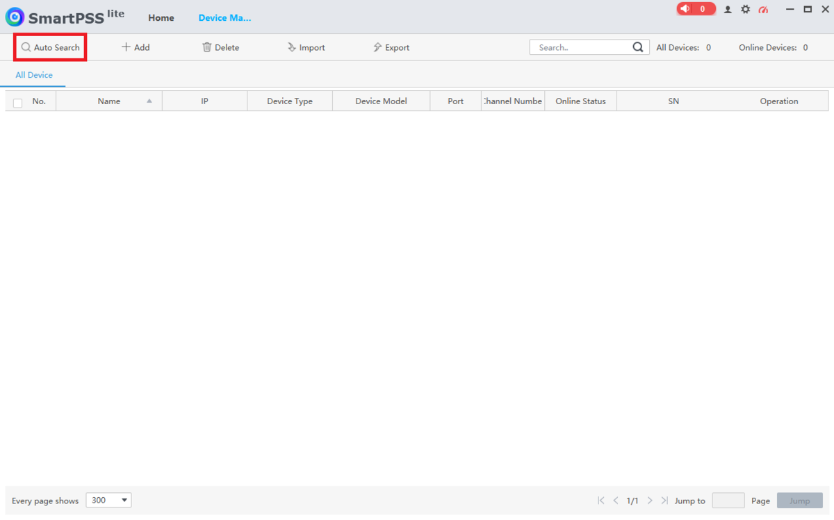
2. Select Auto Search at the top
3. Search through the list of devices and check the box next to the ASC3202B.
If it says “Uninitialized” next to the device in the list, select Initialization at the top.
If it says “Initialized”, skip to Step 8
4. Enter a password in the Password field.
Type the same password in the Confirm Password field.
Select Next at the bottom
5. In the field titled Bind Email Address, enter an email address that will be used to reset the password of the ASC3202B in the case that you forget it.
Then select Next at the bottom
6. Enter a new IP address for the ASC3202B in the New IP field.
Enter the appropriately matching subnet in the Subnet Mask field.
Enter the appropriately matching gateway in the Gateway field.
Then select Finish at the bottom
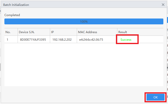
7. Once the ASC3202B has been successfully initialized it will show “Success” under “Results”.
Once that has been completed, select OK
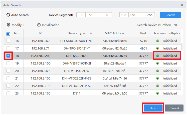
8. It will now show “Initialized” next to the ASC3202B in the list.
Check the box next to it.
Then select Add at the bottom
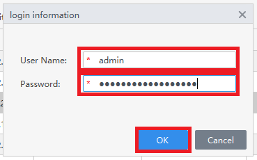
9. Enter the username of the ASC3202B in the User Name field.
Enter the password of the ASC3202B in the Password field.
Then select OK
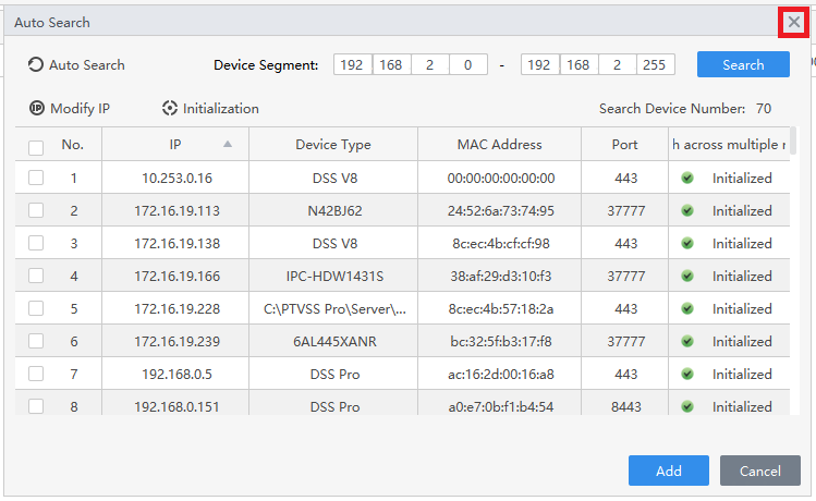
10. Click the X at the top right to close the Auto Search window
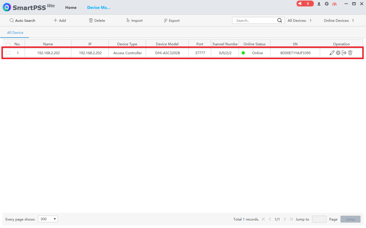
11. You will now see the ASC3202B in the list.
Make sure to verify that it says “Online” under “Online Status”
Creating New Users
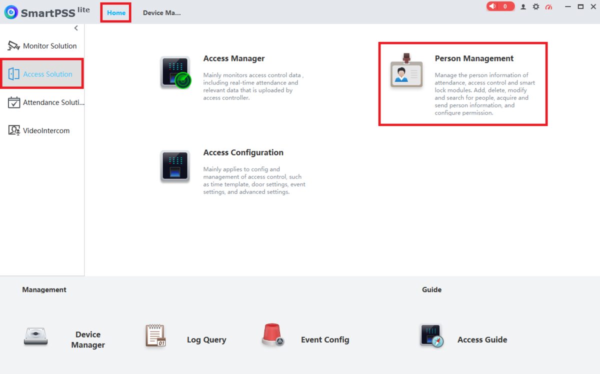
1. Select Home at the top of SmartPSS Lite.
Select Access Solution on the left.
Then select Person Management
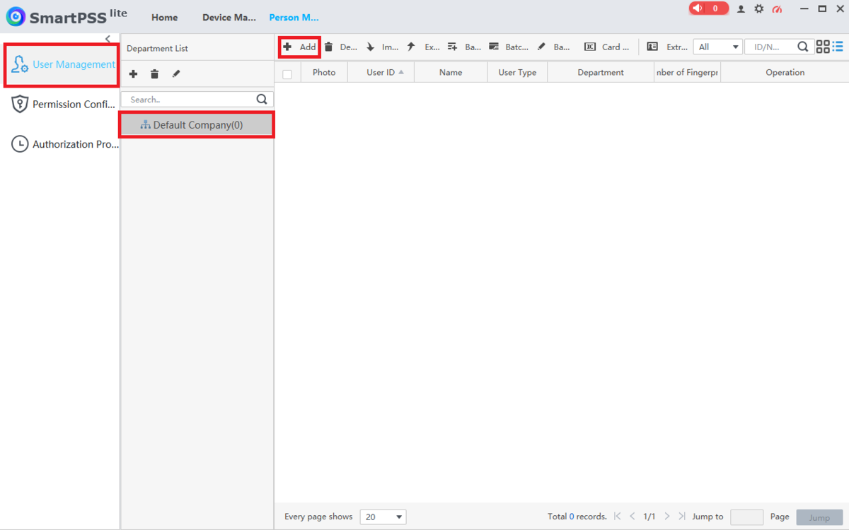
2. Select User Management on the left.
Select the Department or Sub-department from the “Department List”.
Then click on + Add
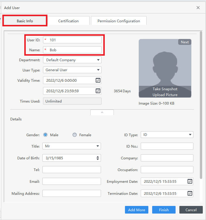
3. Select the Basic Info tab at the top.
Input a numberical ID number in the User ID field.
Then enter the name of the user in the Name field.
Adjust and fill in any other settings and fields on this page
4. Select the Certification tab at the top.
If you want to give this user a numberical code for unlocking the doors on the access controller, select Add next to “Password”, otherwise skip to the next step.
Enter a numerical code in the New Password field. (Passwords can be anywhere from 1 to 8 digits long.)
Enter the same numerical code in the Confirm Password field.
Then click OK
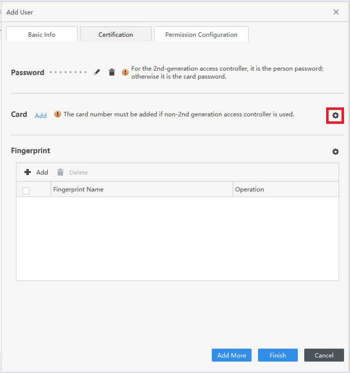
5. If you want to assign a card to this user, first select the Gear icon to the right of “Card”, otherwise skip to Step 9
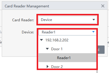
6. Click on the drop-down next to “Card Reader” and either select Card Issuer if you are using a USB card enrollment device connected to your computer, or Device if you are using a card reader that is already wired to the ASC3202B.
If you selected Device, click on the drop-down next to “Device” and select which reader you plan to use to scan in the card for this user.
Then click on OK
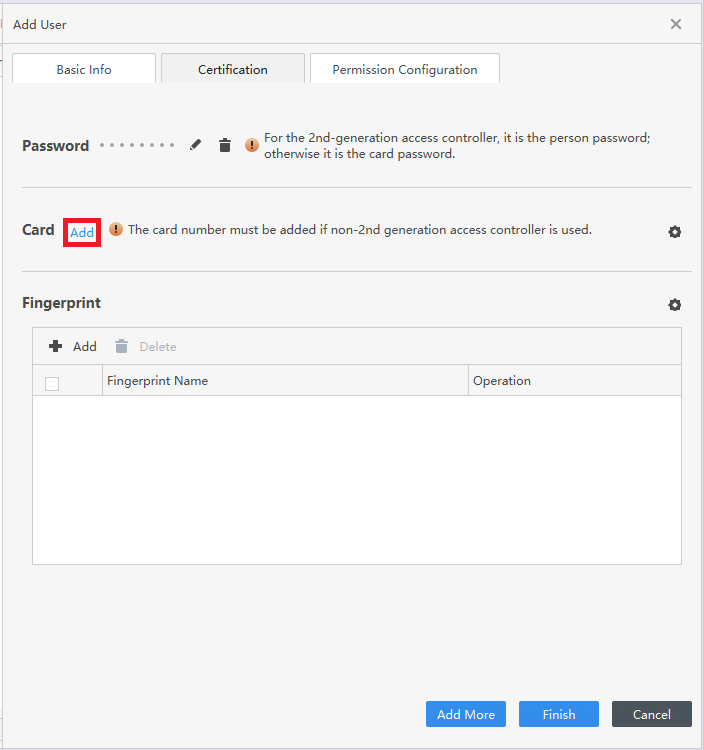
7. Select Add next to “Card”
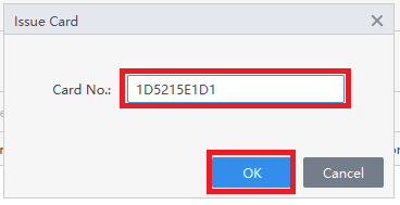
8.Scan the card on the physical reader connected to the connections on the ASC3202B associated with your selection from Step 6 above.
Once the card number appears in the field, click on OK
9. If you want to add a fingerprint to this user, first select the Gear icon to the right of “Fingerprint”, otherwise skip to Step 14
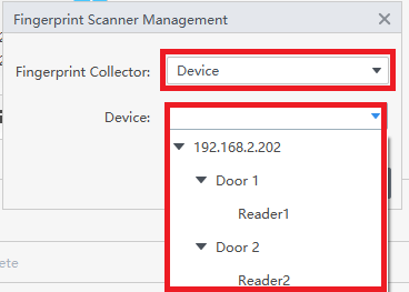
10. Click on the drop-down next to “Fingerprint Collector” and either select Fingerprint Scanner if you are using a USB fingerprint enrollment device connected to your computer, or Device if you are using a fingerprint reader that is already wired to the ASC3202B.
If you selected Device, click on the drop-down next to “Device” and select which reader you plan to use to scan in the fingerprint for this user.
Then click on OK
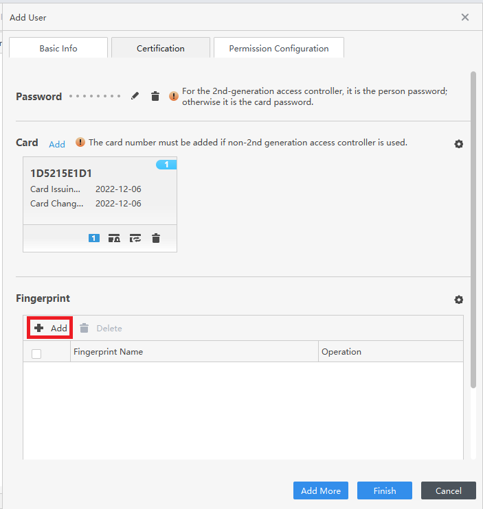
11. Select + Add below “Fingerprint”
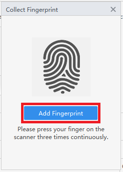
12. Select Add Fingerprint
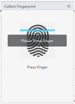
13. When it says “Please Press Finger”, place a finger on the fingerprint scanner connected to the connections on the ASC3202B associated with your selection from Step 10 above.
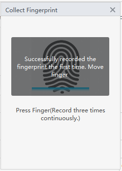
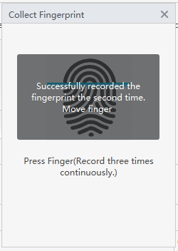
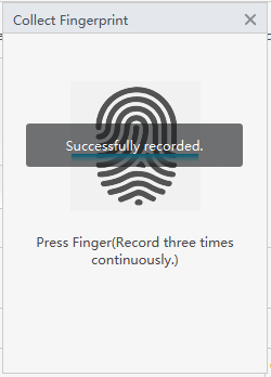
Once it says “Successfully recorded the fingerprnt the first time”, lift up the finger and press it down again. Do this a total of 3 times, until it says “Successfully recorded”
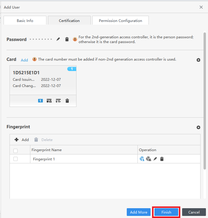
14. Once you are done adding a password, cards, and fingerprints, select Finish at the bottom
15. Now that the user has been added, you will see them in the list
Configuring User Permissions
1. Select Home at the top of SmartPSS Lite.
Select Access Solution on the left.
Then select Access Configuration
2. Select Time Template on the left.
Then select + Add at the top ot create a new Time Template
3. Enter a name for the Time Template you are creating in the Template Name field.
Optionally, put in any other extra information in the Description field.
Select the Week Plan tab and then modify the schedule for each day of the week below.
Then select Save at the bottom
4. You’ll see the Time Template you just created in the list
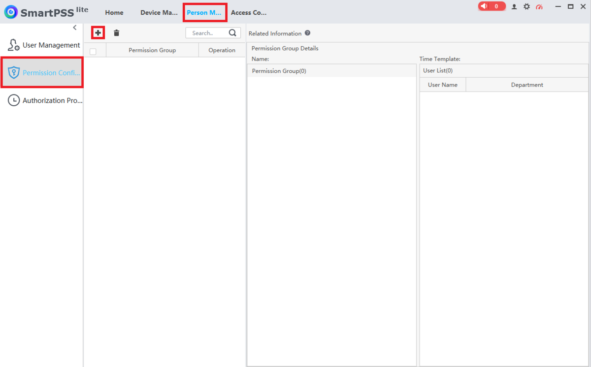
5. Select the Person Management tab at the top. (If you have closed it you can navigate to it via Home -> Access Solution -> Person Managment).
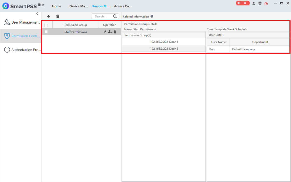
Select Permission Configuration on the left.
Then click on the + button at the top
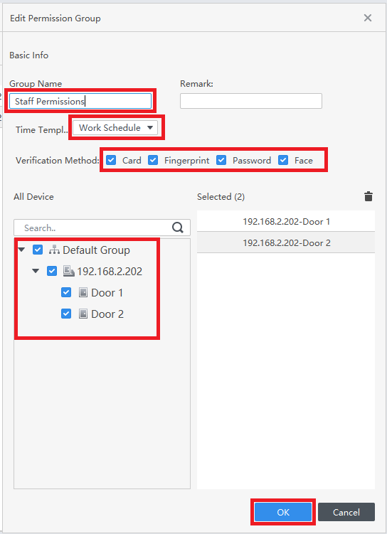
6. Enter the name for this permission group in the Group Name field.
Select the Time Template you want to use from the drop-down list labeled Time Template.
Check the boxes next to all the options you want to allow to unlock this group of doors, next to Verification Method.
Then check all the doors you want to include in this group at the bottom left.
Click on OK at the bottom
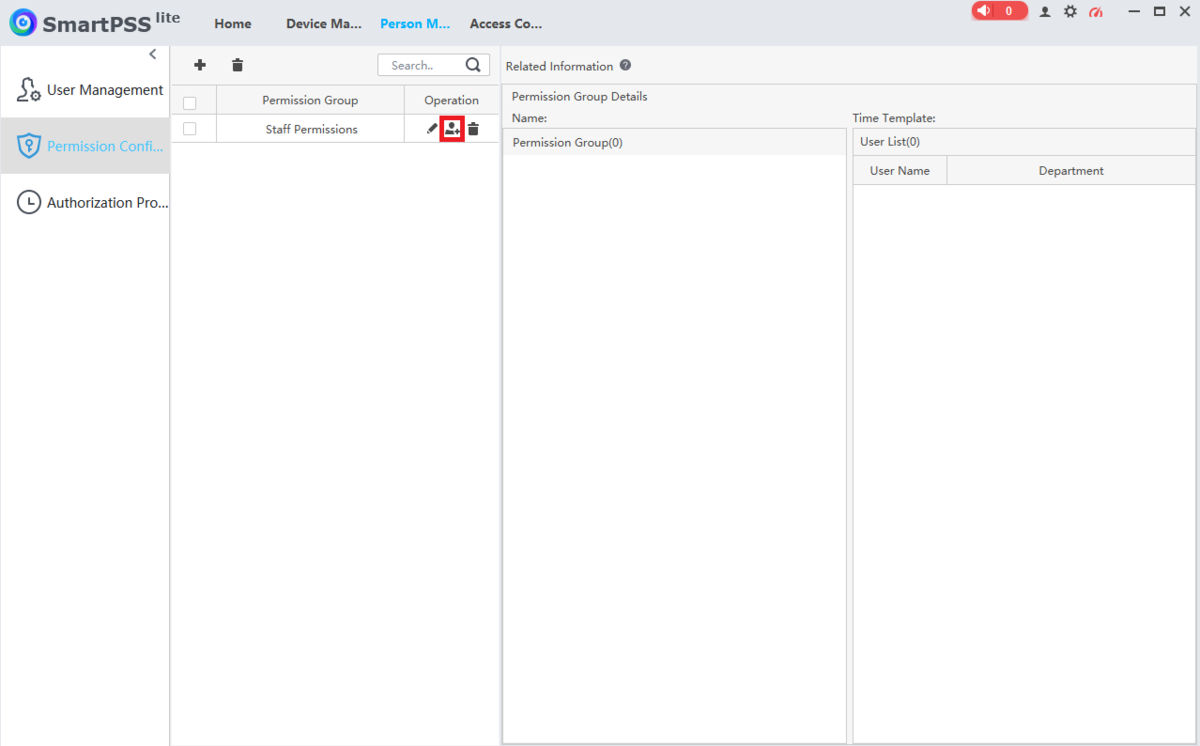
7. Select the Add a User icon under “Operation” next to the Permission Group you just created
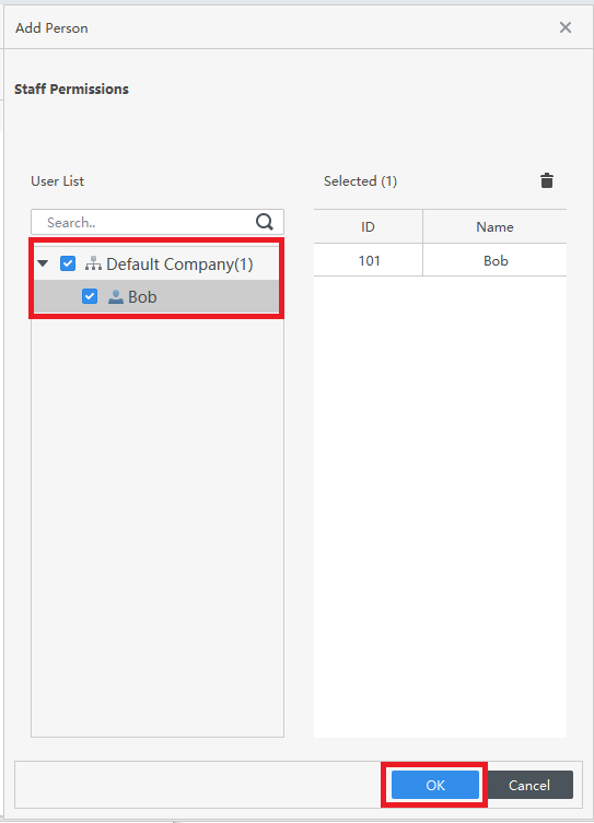
8. Check the boxes next to all the users on the left that you want to add to this Permission Group.
Then click OK at the bottom
9. You will see the Permission Group with the saved permissions in the list
